A detachable anchoring tool and its removal method

A tool and anchoring technology, applied in construction, sheet pile walls, foundation structure engineering, etc., can solve the problems of high processing precision, troublesome assembly, waste of materials, etc., and achieve the effect of low processing cost, simple disassembly, and simple structure

Inactive Publication Date: 2015-12-23
李小川
View PDF13 Cites 0 Cited by
  • Summary
  • Abstract
  • Description
  • Claims
  • Application Information

AI Technical Summary

Problems solved by technology

[0007] The above-mentioned basic types of detachable anchoring appliances will have defects in varying degrees during use, such as: the clip type has the disadvantages of high processing precision, many assembly parts, and troublesome assembly; the U-type type has the disadvantages of steel Stranded wires can only be used in even numbers, which wastes materials, and more than several tons of pulling force must be applied externally when dismantling; for the type of strong pull failure, nearly 20 tons of pulling force is required to forcibly pull the steel strands when dismantling. And in the process of use, if overload occurs, it is very prone to accidents; the P-type lock type has the lowest overall tensile strength under the same conditions and needs to waste a steel strand, and it needs to be removed first After the steel strand for unlocking is pulled out with several tons of pulling force, the steel strand for other work can only be pulled out by applying a considerable force mechanically.
[0008] In addition, there is a common shortcoming in the detachable anchoring appliances of the above several basic forms, that is, when dismantling, it is necessary to install equipment at the outer end of the soil, forcefully pull the steel strand, and place the steel strand Remove the lock at the outer fixed end, and then adopt different removal methods according to the different fixing methods at the inner end of the soil. Basically, it is necessary to use the external force of the equipment to forcibly pull out the steel strand, which is time-consuming and laborious.
[0009] If the operating space is restricted by the environment and the installation and removal equipment cannot be installed (for example, after the building foundation pit is built in the basement, the usable space left between the outer wall of the basement and the waist beam of the slope protection pile is sometimes only a few tens of centimeters) , the lock at the outer end of the steel strand cannot be removed, and the steel strand in the soil will also be unable to go

Method used


Image

  • A detachable anchoring tool and its removal method
  • A detachable anchoring tool and its removal method

Examples


Embodiment 1

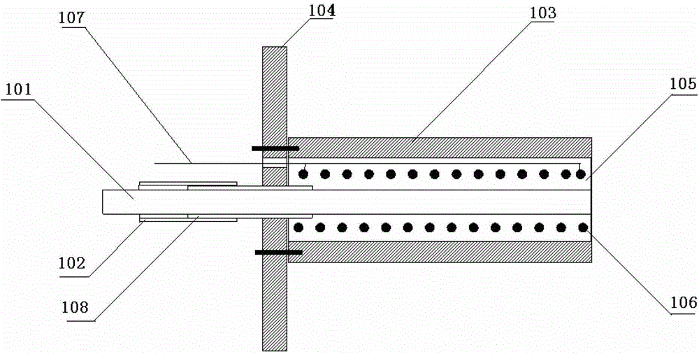
[0036] Such as figure 1 As shown, a detachable anchoring tool of the present invention includes a steel strand 101 and a lock for locking the distal end of the steel strand 101. The exposed section of the steel strand 101 is covered with a sleeve 102, and the lock includes a cylinder 103, the proximal end of the barrel 103 is fixed with a pressure bearing plate 104, and the barrel 103 is filled with a heat-damaged high-strength material 105, an electric heater 106 is pre-embedded in the heat-damaged high-strength material 105, and the electric heater 106 is connected with a conductive wire 107, The conductive wire 107 passes through the barrel 103 and extends outward, and the distal end of the steel strand 101 passes through the pressure plate 104 into the barrel 103 and is locked by the heat-damaged high-strength material 105 .

[0037] Wherein, the casing 102 can be made of (PVC) plastic casing, the cylinder body 103 is preferably a metal cylinder structure, the pressure bea...

Embodiment 2

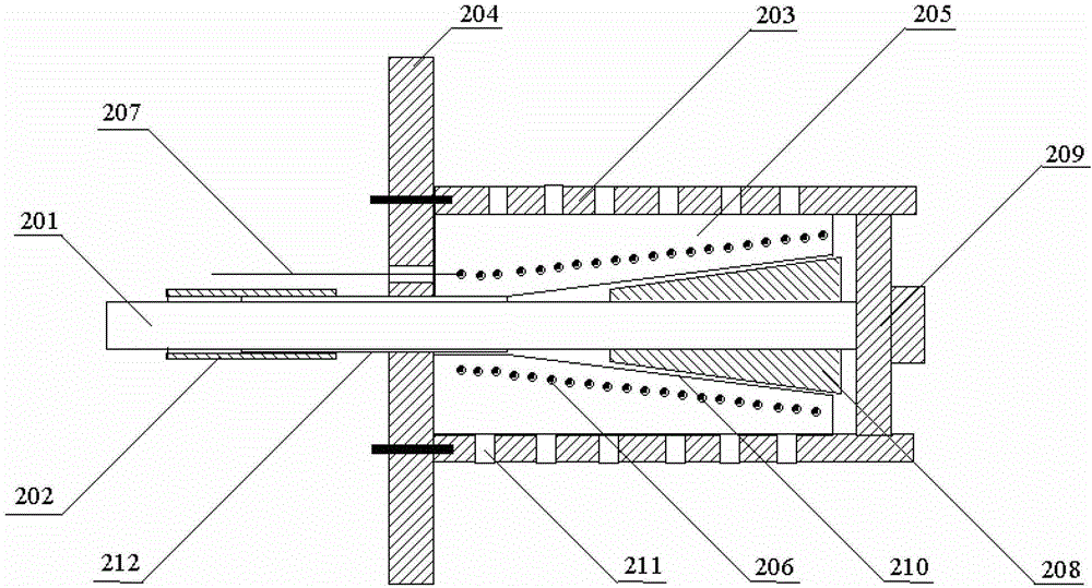
[0042] Such as figure 2 As shown, it is another form of detachable anchoring appliance, which further improves the anchoring appliance in Embodiment 1, specifically including steel strands 201 and locks for locking the distal ends of steel strands 201, steel strands 201 The exposed section of the stranded wire 201 is covered with a sleeve 202, the lock includes a cylinder 203, the proximal end of the cylinder 203 is fixed with a pressure bearing plate 204, the cylinder 203 is filled with a heat-damaged high-strength material 205, and the heat-damaged high-strength material 205 is An electric heating body 206 is pre-embedded, and the electric heating body 206 is connected with a conductive wire 207, and the conductive wire 207 passes through the cylinder body 203 and extends outward; the above-mentioned detachable anchoring device also includes: a toothed mouth is opened on the contact surface with the steel strand 201 The wedge-shaped clamp 208, the heat-damaged high-strength...


PUM


Abstract

The invention discloses a demountable anchoring tool and a demounting method of the demountable anchoring tool. The demountable anchoring tool comprises a steel strand and a lockset used for locking the far end of the steel strand, the exposed section of the steel strand is sleeved with a sleeve pipe, the lockset comprises a barrel, a pressure bearing plate is fixed to the near end of the barrel, the barrel is filled with heat loss type high-strength materials, electric heating bodies are pre-buried in the heat loss type high-strength materials and are connected with a conductive wire, the conductive wire penetrates out of the barrel and extends outwards, and the far end of the steel strand penetrates through the pressure bearing plate, enters the barrel and is locked by the heat loss type high-strength materials. In the demounting process, the conductive wire is powered on, the electric heating bodies heat, the heat loss type high-strength materials are heated and damaged, binding force on the steel strand is lost, the steel strand automatically pops outwards under the action of the elasticity of the steel strand, and automatic demounting is achieved. The demountable anchoring tool is simple in structure, and can be conveniently demounted without arranging tensile equipment outside in the demounting process.

Description

technical field [0001] The invention relates to the field of geotechnical engineering, in particular to a detachable anchoring tool and a removal method thereof. Background technique [0002] Anchor tools are widely used in geotechnical engineering fields such as building foundation pits, roads, bridges, ports, etc., but when they are no longer used, they will lose their meaning and be placed underground, and it is difficult to remove them. [0003] With the development of cities, underground space has also become a scarce resource. However, when developing underground space, such as building subways, underground buildings, underground pipelines, and building support piles, these abandoned anchoring devices have become obstacles and have to be Demolitions add cost, but sometimes the difficulty of demolition makes the construction of new buildings impossible. [0004] In order to solve the problem in this development, the detachable anchoring appliance has just emerged at th...

Claims


Application Information

Patent Timeline
Patent Type & Authority Patents(China)
IPC IPC(8): E02D5/74
Inventor 李小川赵都都李保国
Owner 李小川
Why Eureka
Try Eureka