

Lens for head-mounted display equipment and head-mounted equipment
A display device and lens technology, applied in optical components, optics, instruments, etc., can solve the problems of high cost and high system heat generation, and achieve the effects of stable production performance, LCA aberration correction, and easy molding.
- Summary
- Abstract
- Description
- Claims
- Application Information
AI Technical Summary
Problems solved by technology
Method used
Image

Examples
Embodiment 1
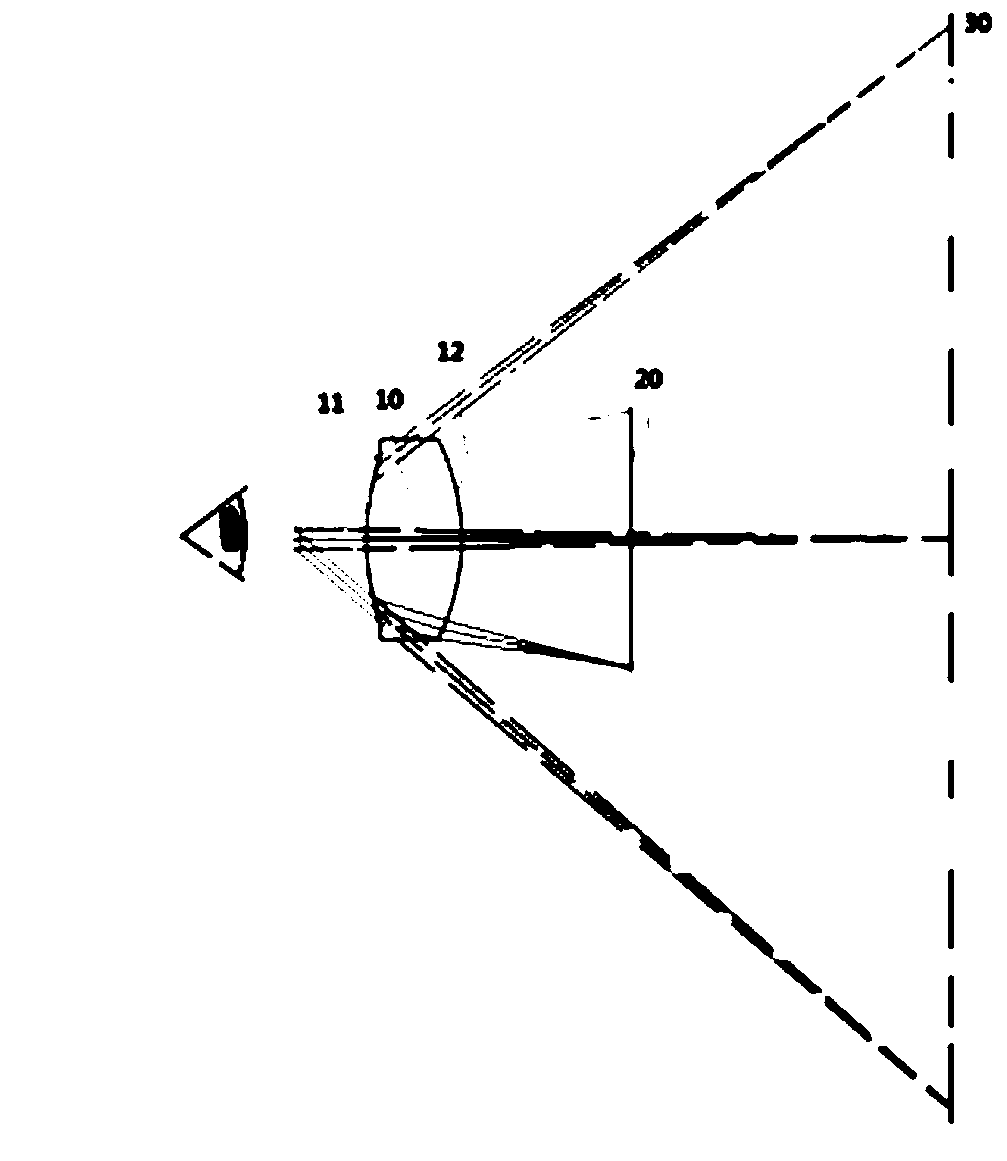
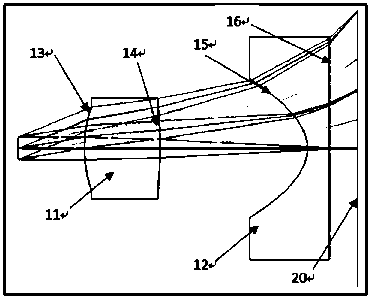
[0030] refer to figure 1 , the present invention is used for a lens for a head-mounted display device, including a biconvex lens 11 and a plano-concave cylindrical mirror 12 arranged side by side; Far away from the human eye side; the biconvex lens 11 includes aspheric surface I13 and aspheric surface II14, and the plano-concave cylindrical lens includes aspheric surface III15 and aspheric surface IV16; the aspheric surface I13 is close to the human eye, and the aspheric surface II14 and aspheric surface III15 are paired Set, the aspherical surface Ⅳ16 is a plane.
[0031] The radii of curvature of aspheric surface Ⅰ13, aspheric surface Ⅱ14, aspheric surface Ⅲ15 and aspheric surface Ⅳ16 are R1, R2, R3 and R4, where R1>0, R2<0, R1<-R2<100, R3<0, R4 is infinite .
[0032] The aspheric surface I13 is smaller than the negative aspheric surface II14, so that the positive lens sheet 1 bears more focal power and plays the role of converging.
[0033] The design value of R3 is sele...
Embodiment 2
[0046] The difference between this embodiment and Embodiment 1 is that the aspheric surface I, aspheric surface II and aspheric surface III of this embodiment are odd-order aspheric surfaces, and their surface shapes satisfy the formula:
[0047] Z = cY 2 1 + 1 - ( 1 + k ) c 2 Y 2 + Σ i = 1 N α i Y i ,
[0048] where z is the coordinate along the optical axis, Y is the radial coordinate in units ...
PUM
 Abstract
Description
Claims
Application Information