
Cutter disc structure for TBM (tunnel boring machine)
A cutter head and hob technology, which is applied in mining equipment, earthwork drilling, tunnels, etc., can solve the problems of low rock breaking efficiency, small excavation area, and large torque on disc hobs, and improve rock breaking efficiency. Efficiency, reducing wear and improving excavation efficiency
- Summary
- Abstract
- Description
- Claims
- Application Information
AI Technical Summary
Problems solved by technology
Method used
Image

Examples
Embodiment Construction
[0015] The present invention will be further described through specific embodiments below in conjunction with the accompanying drawings.
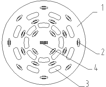
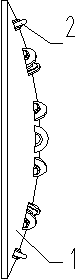
[0016] As shown in the figure, a cutterhead structure for TBM, one side of the cutterhead body 1 is fixed on the TBM body, the working surface on the other side is a spherical surface, a central mounting hole is set at the apex of the working surface, and A center hob unit 4 is arranged in the center mounting hole, and the center hob unit 4 is formed by connecting four hobs sequentially through cutter shafts. On the working surface of the cutter head body 1, the The central axis is the center of the circle, and a plurality of installation holes are evenly arranged on multiple circles with different radii, and an earth-rock discharge hole 3 for earth-rock discharge is evenly arranged between two adjacent rings of installation holes, and an earth-rock discharge hole 3 is arranged in the installation holes respectively. To break the hob 2 of t...
PUM
 Abstract
Description
Claims
Application Information