Extreme group turnover fixture

A technology of extremely group turnover fixtures and splints, which is applied in the direction of rigid containers, containers, packaging, etc., and can solve problems that are not suitable for mechanized operations

Inactive Publication Date: 2016-08-24
长兴大宇科机电有限公司
View PDF6 Cites 0 Cited by
  • Summary
  • Abstract
  • Description
  • Claims
  • Application Information

AI Technical Summary

Problems solved by technology

[0002] At present, the pole group turnover of lead-acid batteries on the market is stacked between pole groups or close to each other, which is not suitable for mechanized operation

Method used


Image

  • Extreme group turnover fixture
  • Extreme group turnover fixture
  • Extreme group turnover fixture

Examples


Embodiment 1

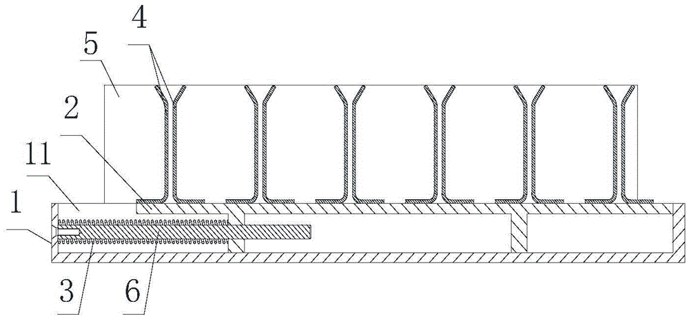
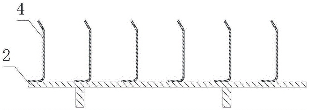
[0019] Such as Figures 1 to 5 As shown, the pole group turnover fixture includes a bottom plate 1 and a sliding plate 2 slidingly fitted with the bottom plate 1. A spring 3 is arranged between the bottom plate 1 and the sliding plate 2. In the direction in which the sliding plate 2 slides relative to the bottom plate 1 The spring 3 has an active force on the base plate 1 and the sliding plate 2. Several clamping plates 4 are arranged on the base plate 1 and the sliding plate 2, and the clamping plates 4 are arranged in a row in the direction in which the sliding plate 2 slides relative to the base plate 1. The splints 4 on the bottom plate 1 and the splints 4 on the sliding plate 2 are distributed at intervals, and the bottom plate 1 is provided with two baffles 5 arranged in parallel, and the baffles 5 are along the direction in which the sliding plate 2 slides relative to the bottom plate 1 Extending, the splint 4 is located between two baffles 5 . The top surface of the b...

Embodiment 2

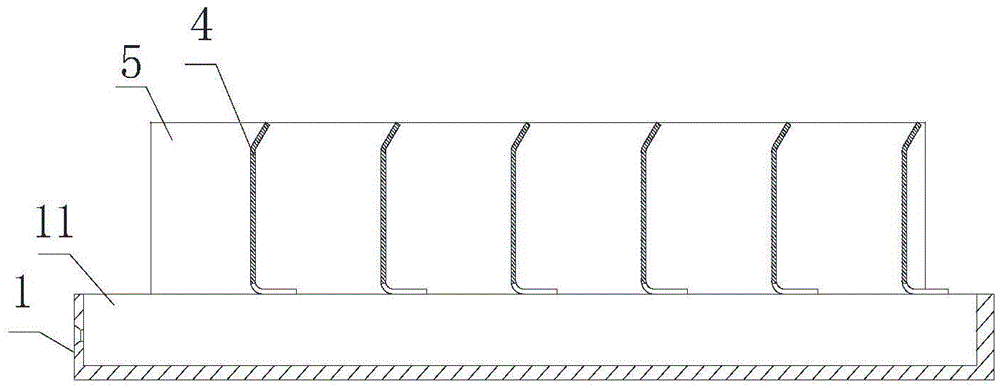
[0022] Such as Figure 7 with 8 As shown, the structure is basically the same as that of Embodiment 1, the difference is that the bottom plate 1 is provided with a long hole 12 that runs through the upper and lower sides of the bottom plate 1, and the splint 4 on the bottom plate 1 is erected above the long hole 12. The sliding plate 2 is arranged in the elongated hole 12, the sliding plate 2 is positioned under the splint 4 on the base plate 1, the length of the elongated hole 12 is greater than the length of the sliding plate 2, and the splint 4 on the sliding plate 2 is set On the top surface of the sliding plate 2, in the width direction of the elongated hole 12, the two ends of the clamping plate 4 on the sliding plate 2 all exceed the scope of the elongated hole so that the clamping plate 4 on the sliding plate 2 is supported on the elongated hole 12, In fact, in this embodiment, the two degrees of freedom of the sliding plate 2 in the axial direction of the long hole a...


PUM


Abstract

The invention provides a pole group turnover clamp, comprising a bottom plate and a sliding plate slidably matched with the bottom plate, a spring is arranged between the bottom plate and the sliding plate, and the spring slides against the bottom plate and the bottom plate in the sliding direction of the sliding plate relative to the bottom plate The plate has an acting force, a plurality of splints are arranged on the bottom plate and the sliding plate, the splints are arranged in a row in the sliding direction of the sliding plate relative to the bottom plate, and the splints on the bottom plate and the sliding plate are distributed at intervals The bottom plate is provided with two baffle plates arranged in parallel, the baffle plates extend along the sliding direction of the sliding plate relative to the bottom plate, and the clamping plate is located between the two baffle plates. After using the pole group turnover fixture, the lead-acid battery pole group is suitable for both manual operation and mechanized operation during turnover, and can also be used for forklift turnover, conveyor chain turnover and other modes.

Description

technical field [0001] The invention relates to a fixture for turnover of lead-acid battery pole groups. Background technique [0002] At present, the pole group turnover of lead-acid batteries on the market is stacked on top of each other or close to each other, which is not suitable for mechanized operation. Contents of the invention [0003] The technical problem to be solved by the present invention is to provide a pole group turnover fixture, which is suitable for both manual operation and mechanized operation during the turnover of the lead-acid battery pole group, and can be used for forklift turnover, conveyor chain turnover and other modes. [0004] In order to solve the above-mentioned existing technical problems, the present invention adopts the following scheme: the extremely group turnover clamp includes a bottom plate and a sliding plate slidingly matched with the bottom plate, a spring is arranged between the bottom plate and the sliding plate, and the botto...

Claims


Application Information

Patent Timeline
Patent Type & Authority Patents(China)
IPC IPC(8): B65D19/22
Inventor 张爱庆张银科包有富
Owner 长兴大宇科机电有限公司
Why Eureka
Try Eureka