Clamp drive circuit

A driving circuit and clamping technology, which is applied in the direction of electrical components, output power conversion devices, etc., can solve the problems of high manufacturing process dependence, high power loss, large current, etc., achieve low process dependence and reduce circuit power consumption Effect

Active Publication Date: 2014-11-19
SHANGHAI ORIENT CHIP TECH CO LTD
View PDF8 Cites 13 Cited by
  • Summary
  • Abstract
  • Description
  • Claims
  • Application Information

AI Technical Summary

Problems solved by technology

The problem with this circuit is that when the input signal IN is at a low level, in order to ensure the rising speed of the driving signal OUT, the driving current of the previous stage must be large enough, which will cause the current flowing through the clamping diode 111 in the clamping state is also very large, resulting in very large power losses
It can be seen that the reliability and stability of the above-mentioned prior art are relatively poor, and the degree of dependence on the manufacturing process is too high

Method used


Image

  • Clamp drive circuit
  • Clamp drive circuit
  • Clamp drive circuit

Examples


Embodiment Construction

[0025] Below in conjunction with the drawings, preferred embodiments of the present invention are given and described in detail.

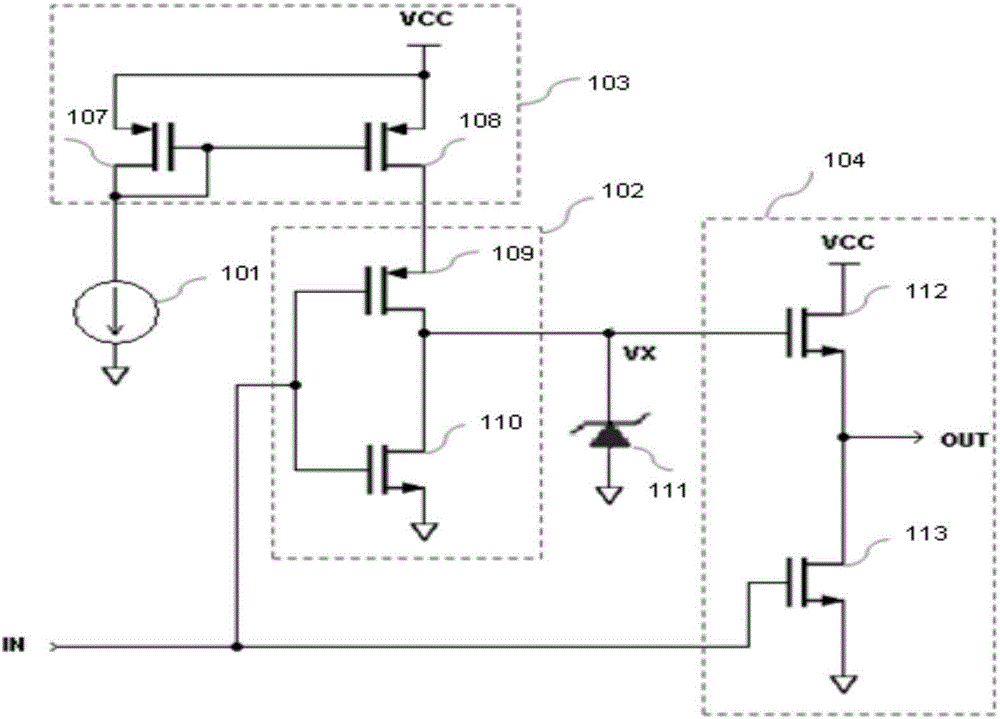
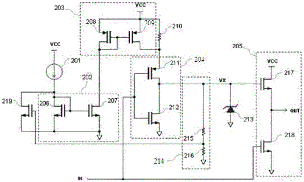
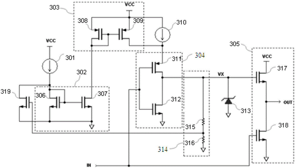
[0026] Such as figure 1 As shown, the present invention, that is, an embodiment of a clamping drive circuit includes: a power supply VCC, a bias current source 201, a switching current mirror 202, an accelerating current mirror 203, an inverter 204, a totem pole output driver 205, a stabilizing Voltage maintaining resistor 210, internal clamping device 213, clamping sampling circuit 214, and current mirror switch tube 219, specifically:

[0027] The input end of the bias current source 201 is connected to the power supply VCC, and its output end is connected to the input end of the conversion current mirror 202;

[0028] The conversion current mirror 202 includes a first MOS transistor 206 and a second MOS transistor 207, wherein the drain of the first MOS transistor 206 is respectively connected to its gate and the output end of the bias current ...


PUM


Abstract

The invention relates to a clamp drive circuit which comprises a bias current source, an acceleration current mirror with a fourth MOS (metal oxide semiconductor) tube, a phase inverter with a fifth MOS tube, a totem-pole output driver with an upper drive tube, a conversion current mirror, a current mirror switch tube used for switching on and off the conversion current mirror, a stable voltage maintaining resistor or a constant current source connected between the source and the drain of the fourth MOS tube, and a clamp sampling circuit connected between the grid of the drive tube and the ground. According to the clamp drive circuit, the conversion current mirror is switched off and the acceleration current mirror is driven through the current mirror switch tube by the clamp sampling circuit so as to completely switch off high drive acceleration current; by adding the stable voltage maintaining resistor or the constant current source, the circuit consumption is reduced while high-speed drive is realized; meanwhile, due to the existence of the stable voltage maintaining resistor or the constant current source, the clamp voltage is stable in the establishment process, and the dependency degree of the whole circuit to a process is low.

Description

technical field [0001] The invention relates to a low power consumption clamp driving circuit applied to a switching power supply. Background technique [0002] As we all know, switching power supply technology has been widely used. In a switching power supply, the signal high level used to drive the power switching device generally does not require an excessively high voltage, because the driving loss is proportional to the square of the high-level voltage, and the excessively high driving voltage will make the power switch The selection of components is limited. For this reason, it is necessary to clamp the driving voltage in terms of safety and performance. [0003] At present, commonly used clamp drive circuits such as figure 1 As shown, the circuit is composed of a bias current source 101, an inverter 102, a driving current mirror 103, a clamping diode 111 and a totem pole output driving circuit 104, wherein the inverter 102 includes a first MOS transistor 109 and a ...

Claims


Application Information

Patent Timeline
Patent Type & Authority Applications(China)
IPC IPC(8): H02M1/08
Inventor 吴玉江张良罗杰罗立权
Owner SHANGHAI ORIENT CHIP TECH CO LTD
Why Eureka
Try Eureka