High range resolution radar capable of emitting multifrequency carrier wave

A range resolution, multi-frequency carrier technology, applied in the field of radar detection, can solve the problems of low anti-jamming and anti-interception performance, and achieve good anti-jamming and anti-interception performance

Active Publication Date: 2014-12-03
HEFEI UNIV OF TECH
View PDF4 Cites 6 Cited by
  • Summary
  • Abstract
  • Description
  • Claims
  • Application Information

AI Technical Summary

Problems solved by technology

[0003] The purpose of the present invention is to disclose a multi-frequency radar device for obtaining high-resolution range images, so as to

Method used


Image

  • High range resolution radar capable of emitting multifrequency carrier wave
  • High range resolution radar capable of emitting multifrequency carrier wave
  • High range resolution radar capable of emitting multifrequency carrier wave

Examples


Embodiment Construction

[0025] Frequency stepping radar is a traditional high-range resolution radar. The radar needs to transmit N narrowband pulses to complete a detection. The carrier frequency difference between adjacent pulses is △f. Then the transmitted nth pulse signal can be expressed as
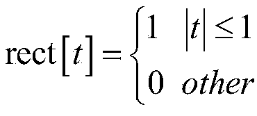
[0026]

[0027] in Represents the rectangular window function, f n = f 0 +n△f is the carrier frequency, T p ,T r , f 0 and represent the pulse duration, pulse repetition frequency, initial frequency and initial phase, respectively.

[0028] For a stationary target whose distance from the radar is R, the reflected echo is

[0029] s n ( t ) = σrect [ 2 ( t - n T r - τ )...


PUM


Abstract

The invention discloses a high range resolution radar device capable of emitting a multifrequency carrier wave. The high range resolution radar device comprises an emitter, a receiver and a signal processing unit. The emitter comprises a multifrequency carrier wave generation module, a mixer, a local oscillator source, a band-pass filter, a coupler and an emitting antenna. The receiver comprises a reception antenna, a mixer, a low pass filter, a 90-degree phase shifter and ADC modules. The two ADC modules are connected to the signal processing unit. The signal output end of the signal processing unit is connected with the multifrequency carrier wave generation module. The high range resolution radar device can obtain non-fuzzy measurement distance which is the same with that of a frequency stepping radar with pulses, the number of which is far less than that of the frequency stepping radar, that is, a high-resolution range profile is obtained; and better anti-interference and anti-interception performance are achieved.

Description

technical field [0001] The invention relates to the field of radar detection, in particular to a high-range resolution radar for transmitting multi-frequency carriers. Background technique [0002] Frequency stepping radar is a kind of high-resolution radar, which has broad application prospects in military and civilian fields. Its basic process of obtaining high-range resolution is: sequentially transmitting a set of narrow-band pulse trains, and the transmission waveform of each pulse It is a single-frequency carrier signal that is uniformly stepped according to a fixed frequency difference. At the receiving end, the echo signal is mixed with a reference local oscillator signal with the same frequency as the transmitted signal. The mixed zero-IF signal can be obtained by orthogonal sampling. The complex sampling value of a group of target echo signals, and the inverse discrete Fourier transform is performed on this group of complex sampling values, and the high-resolution ...

Claims


Application Information

Patent Timeline
IPC IPC(8): G01S13/02G01S7/36
CPCG01S7/36G01S13/12G01S13/24
Inventor 尹治平桑磊杨军张艳梅
Owner HEFEI UNIV OF TECH
Why Eureka
Try Eureka