Range Dimension High Resolution Imaging Method Using Signal Discrete Frequency Components

A technology of discrete frequency and imaging method, applied in the field of array imaging, which can solve the problems of increased system cost and difficult realization of hardware system

Active Publication Date: 2018-03-30
NORTHWESTERN POLYTECHNICAL UNIV
View PDF3 Cites 0 Cited by
  • Summary
  • Abstract
  • Description
  • Claims
  • Application Information

AI Technical Summary

Problems solved by technology

This not only faces the problem that the hardware system is difficult to realize, but also leads to a significant increase in system cost

Method used


Image

  • Range Dimension High Resolution Imaging Method Using Signal Discrete Frequency Components
  • Range Dimension High Resolution Imaging Method Using Signal Discrete Frequency Components
  • Range Dimension High Resolution Imaging Method Using Signal Discrete Frequency Components

Examples


Embodiment Construction

[0021] The present invention will be further described below in conjunction with the accompanying drawings and embodiments, and the present invention includes but not limited to the following embodiments.

[0022] Main content of the present invention has:

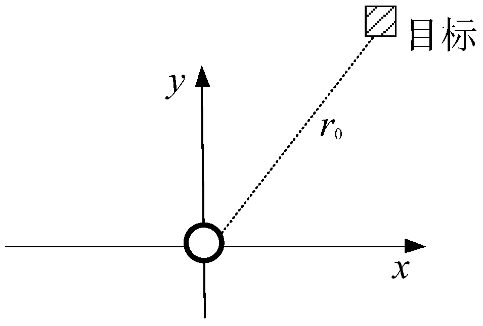
[0023] 1. Use a single transceiver array element to transmit a signal with a certain bandwidth (the bandwidth is determined by the effective bandwidth of the system), collect the echo and extract a group of L discrete frequency components X in the echo, where each row of X represents A discrete frequency component. The frequency of this group of discrete frequency components is L×1 dimension column vector f=[f 1 , f 2 ,..., f L ] T , where f l Represents the frequency of the l (l=1,2,…,L) discrete frequency component, [] T Indicates a transpose. The signal travels from launch to target to reception with a propagation distance of 2r 0 , so the phase delay of this set of discrete frequency components can be expressed...


PUM


Abstract

The invention provides a distance dimension high-resolution imaging method utilizing a signal discrete frequency component. The method comprises the following steps: transmitting a signal with certain bandwidth by utilizing a single receiving-transmitting combined array; extracting one group of L discrete frequency components in echoes; determining different phase delays which are generated after the L discrete frequency components are transmitted for the same distance; constructing an L*L dimension covariance matrix by using the extracted L discrete frequency components; designing distance dimension weight vectors to be subjected to beam forming along the distance dimension to obtain an effect formed by distance dimension beams; and meanwhile, carrying out high-resolution processing on a covariance matrix along the distance dimension to obtain a high-resolution distance image. With the adoption of the distance dimension high-resolution imaging method provided by the invention, the distance resolution can be improved by using limited system bandwidth and the high-resolution distance image can be obtained.

Description

technical field [0001] The invention relates to an array imaging method. Background technique [0002] In the existing imaging systems such as imaging radar and imaging sonar, in order to improve the distance resolution, it is necessary to use a larger bandwidth transmission signal (Bao Zheng, Xing Mengdao, Wang Tong. Radar Imaging Technology. Electronic Industry Press, 2004.) . However, in order to process signals with a larger bandwidth, it is necessary to increase the instantaneous bandwidth of the imaging system transmitter and receiver (M.C.Knight, R.G.Pridham, S.M.Kay.Digital signal processing for sonar.Proc.IEEE,1981,69(11):1451 -1506). This not only faces the problem that the hardware system is difficult to realize, but also leads to a significant increase in system cost. Contents of the invention [0003] In order to overcome the deficiencies of the prior art, the present invention provides a method for obtaining a high-resolution range image by utilizing the d...

Claims


Application Information

Patent Timeline
Patent Type & Authority Patents(China)
IPC IPC(8): G01S13/89G01S15/89G01S7/292G01S7/35G01S7/527G01S7/536
CPCG01S7/2923G01S7/354G01S7/527G01S7/536G01S13/89G01S15/89
Inventor 刘雄厚孙超杨益新卓颉
Owner NORTHWESTERN POLYTECHNICAL UNIV
Why Eureka
Try Eureka