Pulse wave radar device

a radar device and pulse wave technology, applied in measurement devices, instruments, using reradiation, etc., can solve the problems of large power consumption and difficult to achieve stable circuit operation, and achieve accurate reception, high distance resolution, and distance measurement

Inactive Publication Date: 2006-12-05
TDK CORPARATION
View PDF20 Cites 12 Cited by
  • Summary
  • Abstract
  • Description
  • Claims
  • Application Information

AI Technical Summary

Benefits of technology

[0012]To cope with this problem, the object of this invention is to provide a pulse wave radar device having a high distance resolution which can measure the distance by accurately receiving the receiving pulse having a large receiving level difference between a receiving pulse wave of a large signal from a near object and a receiving pulse wave of a small signal from a remote object.
[0030]Also, according to the invention, there is provided a pulse wave radar device having a receiving circuit capable of variable gain amplification and detection with a simple circuit configuration and small in power consumption.

Problems solved by technology

Thus, the AGC operation as the negative feedback control system becomes unstable and the stable circuit operation is difficult to achieve.
Also, in the conventional variable attenuation circuit used for the amplifier circuit, each PIN diode is required to be controlled by a separate DC power supply, and further, the existence of three current paths disadvantageously leads to a large power consumption.

Method used


Image

  • Pulse wave radar device
  • Pulse wave radar device
  • Pulse wave radar device

Examples


Embodiment Construction

[0039]Embodiments of the invention are explained below with reference to the drawings. This invention is not limited to the embodiments described below.

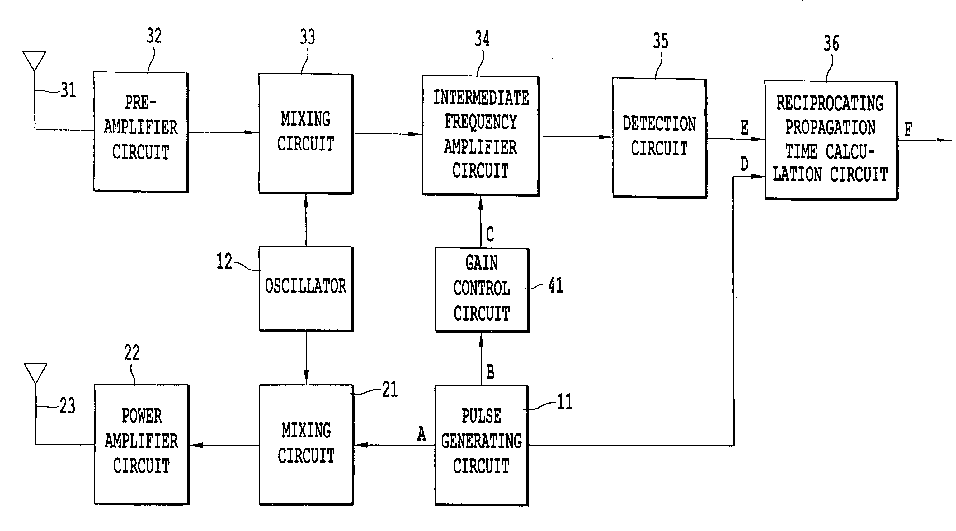
[0040]FIG. 3 is a block diagram for explaining an example of a pulse wave radar device according to an embodiment of the invention. The configuration of the pulse wave radar device is explained with reference to this block diagram. In FIG. 3, numeral 11 denotes a pulse generating circuit for generating transmitting pulses having a predetermined period, numeral 12 denotes an oscillator adapted to oscillate at a modulation frequency, numeral 21 denotes a mixing circuit for modulating the transmitting pulse at a modulation frequency, numeral 22 denotes a power amplifier circuit for amplifying the power of the transmitting pulse wave, numeral 23 denotes a transmitting antenna for radiating the transmitting pulse wave, numeral 31 denotes a receiving antenna for receiving the receiving pulse wave, numeral 32 denotes a pre-amplifier circuit...


PUM


Abstract

A pulse wave radar device controls an amplification degree of a receiving circuit, downward at a time of measuring an object at a short distance immediately after transmission of a transmitting pulse wave and upward, at a time of measuring the object at a long distance, by increasing the amplification degree of the receiving circuit progressively with the lapse of time after the transmission of the transmitting pulse wave.

Description

BACKGROUND OF THE INVENTION[0001]1. Field of the Invention[0002]This invention relates to a pulse wave radar device using the millimeter wave or submillimeter wave band, or in particular to a pulse wave radar device having an improved detection ability for the reflected wave from an object at a short distance.[0003]2. Description of the Related Art[0004]In recent years, a radar DEVICE has come to be mounted on an automotive vehicle for the purpose of collision prevention and auto cruising. In this in-vehicle radar DEVICE, the reciprocating distance to an object is determined by multiplying the velocity of light by the time from the transmission of the transmitting pulse wave to the receiving of the reflected wave from the object. Thus, the distance to the object is calculated by measuring the time required from the transmission of the transmitting pulse wave to the receiving of the reflected wave from the object.[0005]This pulse wave radar device makes the preparation for receiving ...

Claims


Application Information

Patent Timeline
Patent Type & Authority Patents(United States)
IPC IPC(8): G01S7/34G01S7/285G01S13/93G01S13/931
CPCG01S7/34G01S13/931G01S7/285G01S13/76
Inventor IKEDA, HIROSHISHIMODA, HIDEAKIYOKOYAMA, TAKESHI
Owner TDK CORPARATION
Why Eureka
Try Eureka