Underwater detection device and underwater detecting method

a detection device and underwater technology, applied in the field of underwater detection devices and underwater detection methods, can solve problems such as difficult discrimination of bottom sediment at a deep depth, and achieve the effects of shorter pulse width, stronger energy, and high distance resolution

Active Publication Date: 2012-10-18
FURUNO ELECTRIC CO LTD
View PDF10 Cites 15 Cited by
  • Summary
  • Abstract
  • Description
  • Claims
  • Application Information

AI Technical Summary

Benefits of technology

[0009]With this configuration, the detection of at least one of the target object (e.g., fish) and the water bottom depth and the discrimination of the water bottom sediment type are performed based on the ultrasonic waves dedicated for the respective purposes, which have the different pulse widths from each other. The ultrasonic wave for the detection of at least one of the target object and the water bottom depth is required to have a higher distance resolution, that is, a shorter pulse width, so as to detect at least one of a length and kind of the target object, and the water bottom depth. On the other hand, the ultrasonic wave for the water bottom sediment type discrimination is required to have a stronger energy (signal intensity) and a longer detection range and larger SN ratio, that is a longer pulse width. Thus, by using the pulse width of the ultrasonic wave for the water bottom sediment type discrimination longer than the pulse width of the ultrasonic wave for the detection of at least one of the target object and the water bottom depth, both the detection of at least one of the target object and the water bottom depth and the discrimination of the water bottom sediment type can be performed by a single device.

Problems solved by technology

With the shorter transmission pulse width, an energy of the ultrasonic wave drops and a detectable distance range shrinks; thereby, the bottom sediment discrimination at a deep depth is difficult.

Method used


Image

  • Underwater detection device and underwater detecting method
  • Underwater detection device and underwater detecting method
  • Underwater detection device and underwater detecting method

Examples


Embodiment Construction

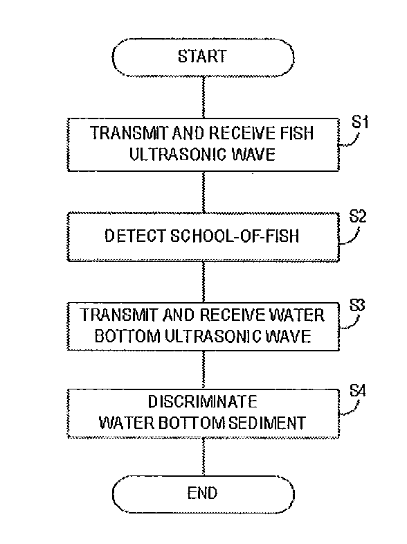
[0029]Hereinafter, a suitable embodiment of a fish finder, an underwater detection device, an underwater detecting method, and a computer readable media storing underwater detecting program according to the present invention is described with reference to the appended drawings. The fish finder 1 transmits an ultrasonic wave pulse (hereinafter, may simply be referred to as “the ultrasonic wave”) from an oscillator toward a water bottom, and receives, by the oscillator, a reflection wave that is the ultrasonic wave reflected on, for example, a school-of-fish or the water bottom. The fish finder 1 performs calculation processing on the received reflection wave, and displays an image (echo data) of the school-of-fish or the water bottom on a display unit based on the processing result. Note that, the term “water bottom” as used herein refers to any water bottom or any water bottom surface at sea, lake, river, etc.

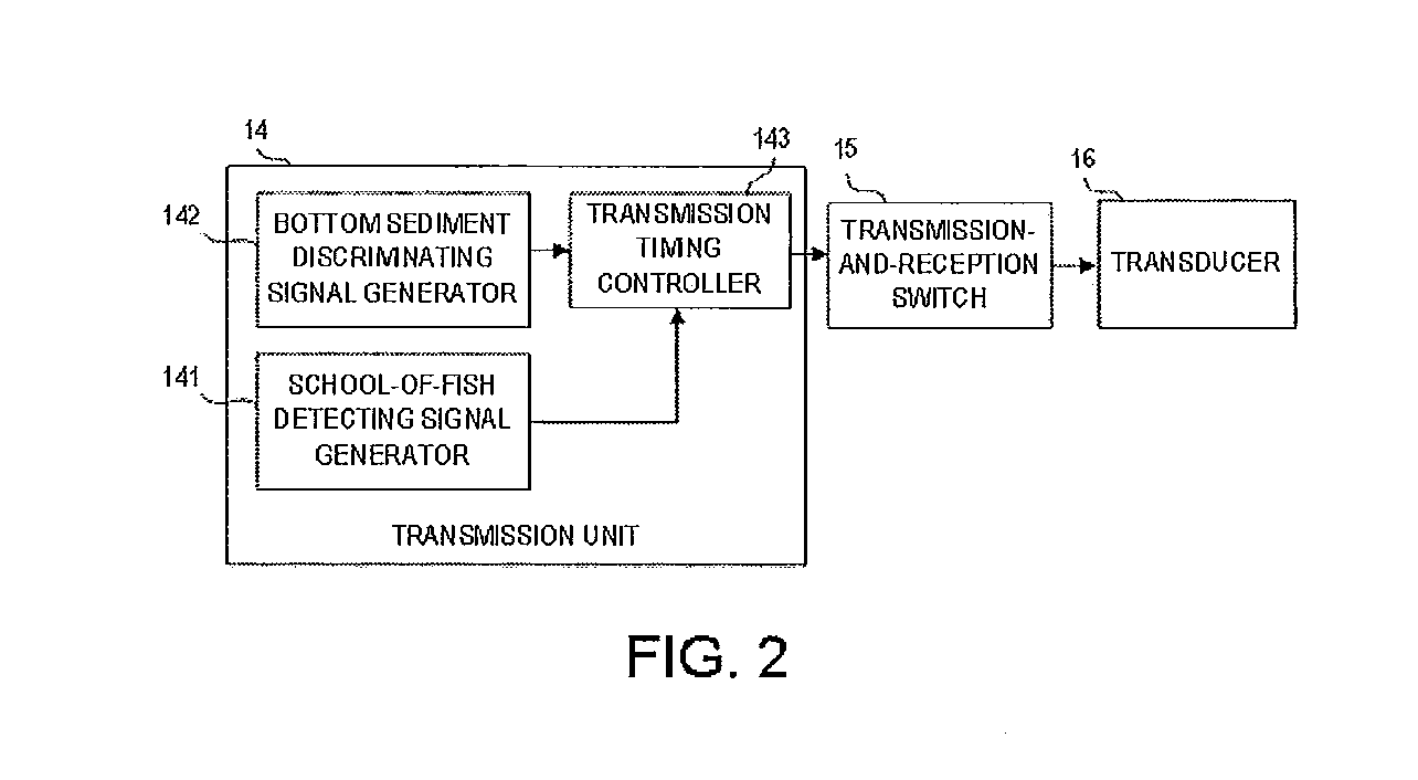
[0030]FIG. 1 is a block diagram schematically showing a configuration of t...


PUM


Abstract

This disclosure provides an underwater detection device, which includes a first generator for generating a first transmission signal, a second generator for generating a second transmission signal having a longer pulse width than that of the first transmission signal, an output unit for outputting the transmission signals generated by the first and second generators to a transducer for transmitting underwater ultrasonic waves based on the first and second transmission signals, respectively, receiving the reflection waves caused by the ultrasonic waves, respectively, and converting the reflection waves into a first reception signal and a second reception signal, respectively, an underwater detector for detecting at least one of a presence of a target object and a water bottom depth based on the first reception signal, and a bottom sediment discriminator for discriminating a water bottom sediment type based on the second reception signal.

Description

CROSS-REFERENCE TO RELATED APPLICATION(S) [0001]The application claims priority under 35 U.S.C. §119 to Japanese Patent Application No. 2011-090436, which was filed on Apr. 14, 2011 the entire disclosure of which is hereby incorporated by reference.[0002]1. Technical Field[0003]The present invention relates to a fish finder, an underwater detection device, an underwater detecting method, and a computer readable media storing underwater detecting program, in which the underwater detection is performed by transmitting an ultrasonic wave underwater and based on a reflection wave caused by the ultrasonic wave.[0004]2. Background of the Invention[0005]Conventionally, as fish finders used for ships, a fish finder for discriminating a sea bottom sediment type (rocks, stones, sand, etc.) and displaying the sediment type has been known (see JP4348415B). The bottom sediment discrimination is performed by analyzing a sea bottom echo of a transmission pulse of an ultrasonic wave. For example, i...

Claims


Application Information

Patent Timeline
Patent Type & Authority Applications(United States)
IPC IPC(8): G01S15/89
CPCG01S7/524G01S15/96G01S15/102G01S7/5276
Inventor YAMAGUCHI, TAKEHARUBORRALLO, NICOLAS
Owner FURUNO ELECTRIC CO LTD
Why Eureka
Try Eureka