
Signal Generating Method and Radar System

a signal generation and radar technology, applied in the direction of reradiation, measurement devices, instruments, etc., can solve the problems of increasing interference between radar systems, and increasing false detection rate, so as to reduce false detection rate, enhance radar performance, and high speed resolution

Active Publication Date: 2014-12-04
WISTRON NEWEB
View PDF6 Cites 14 Cited by
  • Summary
  • Abstract
  • Description
  • Claims
  • Application Information

AI Technical Summary

Benefits of technology

The present invention provides a method for generating signals and a radar system that can identify ghost targets and reduce false detections in a noisy environment. Additionally, it improves radar performance for high-speed and high-distance resolution.

Problems solved by technology

Nevertheless, in an environment with multiple targets (i.e. a noisy environment), interference among radar systems has been greatly increased due to a proliferation of the conventional radar systems.
In other words, a signal received by a radar system may be a transmission signal transmitted by another of the same kind of radar system on a target, but not a reflected signal of the radar system itself, which may result in false detection.
When more radar systems of the same kind exist in the environment, the false detection rate becomes even higher.
Besides, there are many challenges for designing a radar system, such as requirements to distinguish moving targets and steady targets, and to recognize multiple targets and ghost targets.
In addition, the conventional detection algorithm may be too complex and need to be simplified.

Method used


Image

  • Signal Generating Method and Radar System
  • Signal Generating Method and Radar System
  • Signal Generating Method and Radar System

Examples


Embodiment Construction

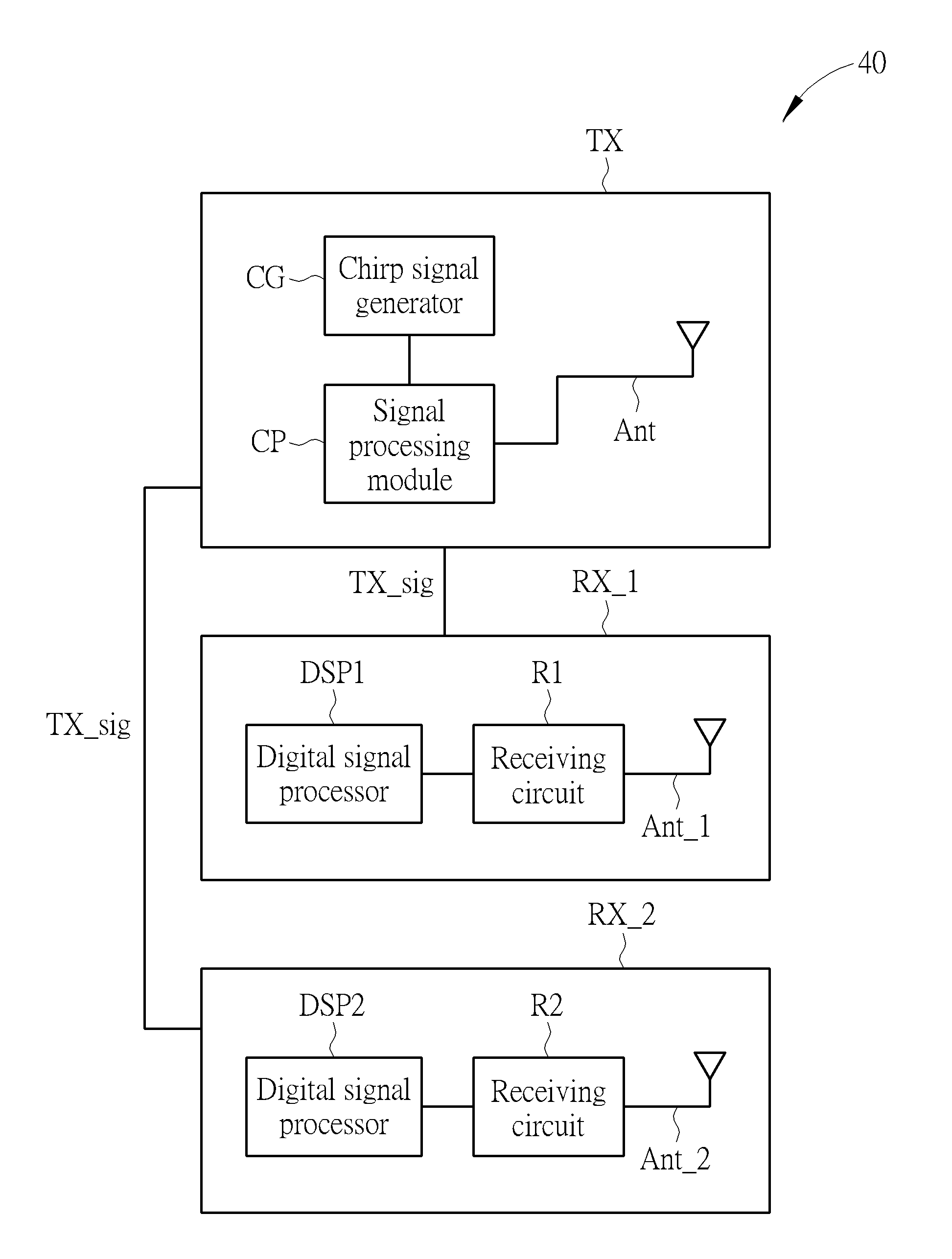
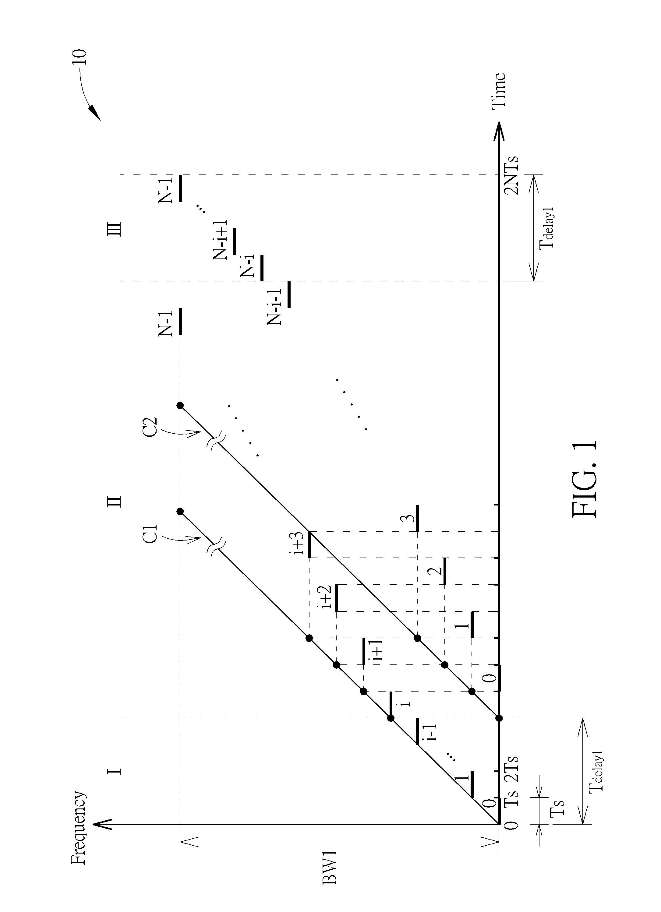
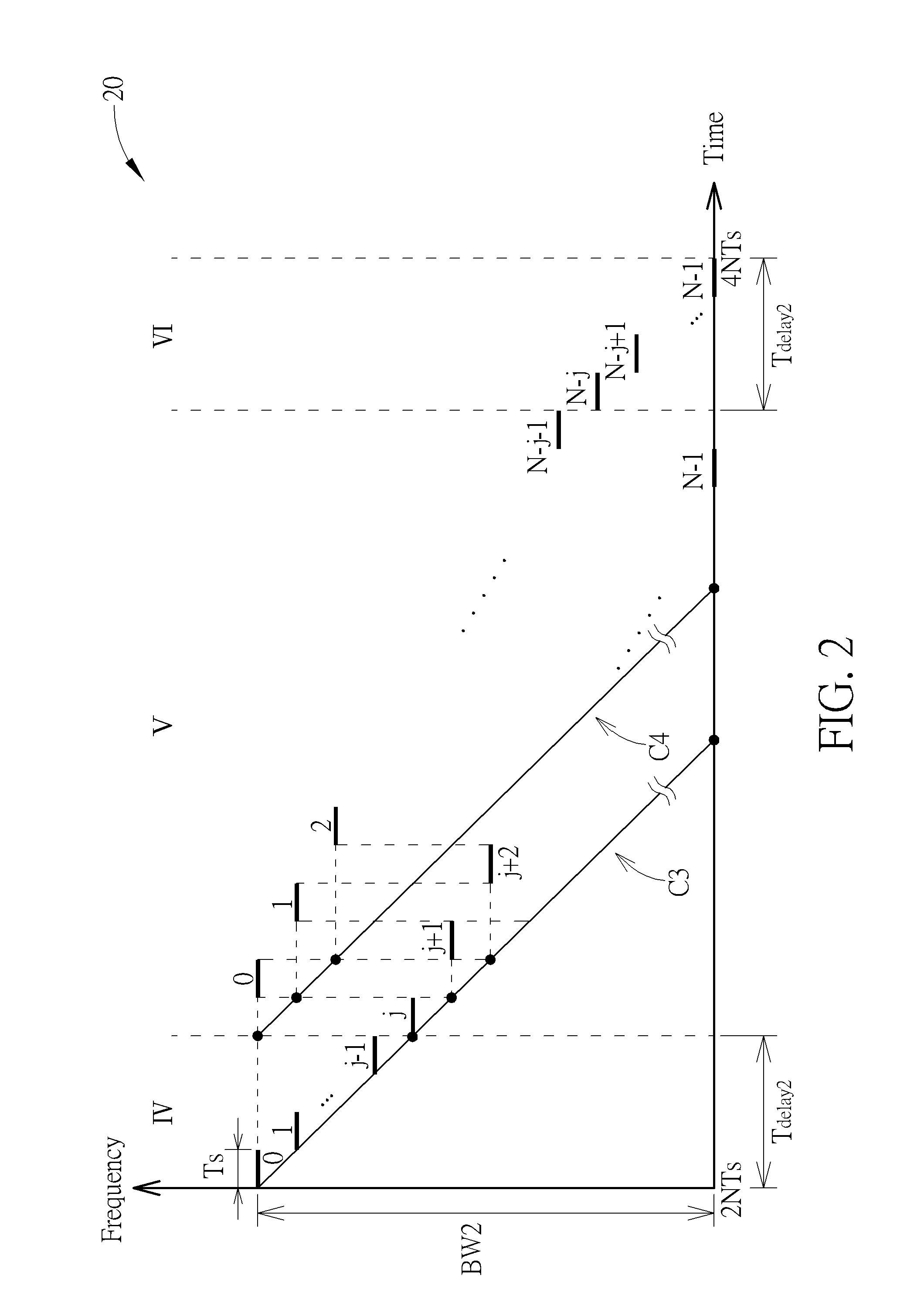
[0016]Please refer to FIG. 1, which is a time-frequency diagram of a frequency modulated signal 10 according to an embodiment of the present invention. The frequency modulated signal 10 is used as a radar transmitting wave in a radar system. The frequency modulated signal 10 includes chirp signals C1 and C2, which are in a form of a linear frequency modulated continuous wave (LFMCW). Both of the chirp signals are N-step linear stepped frequency modulated continuous waves with the same frequency modulation bandwidth BW1. The radar system uses a sample and hold circuit to generate each step of the chirp signals C1 and C2 for transmitting the frequency modulated signal 10. The chirp signal C2 has a time delay Tdelay1 relative to the chirp signal C1. Therefore, the total transmission time of the frequency modulated signal 10 can be divided into durations I-III, wherein the frequency modulated signal 10 includes i steps of the chirp signal C1 in the duration I, an interleaved combination...


PUM


Abstract

A signal generating method for a radar system includes generating a first chirp signal and a second chirp signal having a first time delay relative to the first chirp signal; and combining the first chirp signal and the second chirp signal to determine a frequency modulated signal, wherein the first chirp signal and the second chirp signal are N-step linear stepped frequency modulated continuous waves having the same frequency modulation bandwidth, such that the frequency modulated signal includes i steps of the first chirp signal in a first duration, an interleaved combination of N−i steps of the first chirp signal and N−i steps of the second chirp signal in a second duration, and i steps of the second chirp signal in a third duration.

Description

BACKGROUND OF THE INVENTION[0001]1. Field of the Invention[0002]The present invention relates to a signal generating method and a radar system, and more particularly, to a signal generating method and a radar system capable of differentiating ghost targets, reducing false detection rate significantly, providing high speed resolution and high distance resolution as well as simplifying the detection algorithm.[0003]2. Description of the Prior Art[0004]Generally, different forms of radar transmission waves correspond to different detection methods, and the forms of radar transmission waves and the corresponding detection methods are important factors that affect performance of entire radar systems. In the prior art, transmission waves composed of linear frequency modulated continuous waves (LFMCWs) can be used for estimating distance and speed of a target, and therefore are often applied to a radar system to generate the transmission signal.[0005]Nevertheless, in an environment with mu...

Claims


Application Information

Patent Timeline
Patent Type & Authority Applications(United States)
IPC IPC(8): G01S7/35G01S13/00G01S13/02G01S13/931
CPCG01S7/35G01S13/02G01S13/006G01S13/345G01S7/023G01S13/347G01S13/931G01S7/0232G01S7/0235
Inventor KUO, CHI-CHENGLI, JENG-DA
Owner WISTRON NEWEB
Learn More