Gearbox machining method

A processing method and gearbox technology, applied in metal processing equipment, metal processing machinery parts, manufacturing tools, etc., can solve the problems of high scrap rate and low production efficiency in gearbox processing, achieve flexible and changeable production plans, and reduce labor costs. Strength and the effect of improving processing efficiency

Inactive Publication Date: 2014-12-10
柳州市英利机械铸造有限责任公司
View PDF6 Cites 11 Cited by
  • Summary
  • Abstract
  • Description
  • Claims
  • Application Information

AI Technical Summary

Problems solved by technology

[0003] The problem to be solved by the present invention is to provide a processing method of a gearbox to solve the problems of high processing reject rate and low production efficiency of existing gearboxes

Method used


Image

  • Gearbox machining method
  • Gearbox machining method
  • Gearbox machining method

Examples


Embodiment Construction

[0020] The present invention will be described in further detail below in conjunction with accompanying drawing example:

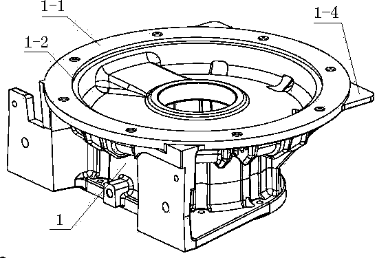
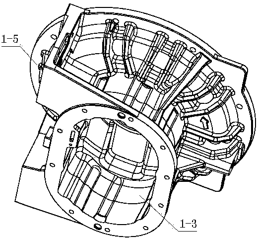
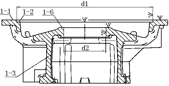
[0021] Figures 1 to 3 Shown is the gear box to be processed, the gear box 1 includes a box body part with waist-shaped holes 1-3 inside and a circular flange connected to the outer edge of one end of the box body part with two ear plates , the bottom surfaces of the two ear plates 1-4 and the bottom surface 1-5 of the circular flange are arranged on the same plane, and the circular flange has a bearing hole connected with the waist hole 1-3; There is a positioning spigot at 1-1 on the upper end surface of the circular flange. The bearing hole and the positioning hole of the locating spigot are arranged coaxially. The diameter of the bearing hole is d2, and the positioning hole of the locating spigot is The hole diameter is d1; according to the process requirements, the upper end surface 1-1 of the gear box round flange, the positioning hole of the positi...


PUM


Abstract

The invention discloses a gearbox machining method and relates to the technical field of machining. A gearbox turn-milling fixture is used for machining gearboxes, and the gearbox machining method comprises the operation steps that A, the fixture is installed, B, parts are installed, and C, machining is carried out, wherein a turning tool is used for turning the upper end face of a round flange disc, a locating hole of a locating seam allowance, the bottom face of the locating hole and the upper end face of a bearing hole; a boring cutter is used for boring the bearing hole; D, a gearbox is dismounted, namely machining of the end face and holes in one side of the round flange disc of the gearbox is finished. Compared with the prior art, the gearbox machining method can solve the problems that an existing gearbox is high in machining injection rate and low in production efficiency.

Description

technical field [0001] The invention relates to the technical field of mechanical processing, in particular to a method for processing the end face and the hole on one side of a circular flange of a gear box. Background technique [0002] There is an existing Figure 1 to Figure 3 Shown gear box, this gear box weighs about 80 kilograms; This gear box 1 includes the box body part that is provided with waist-shaped hole 1-3 and is connected with the outer edge of this box body part one end and is provided with two ear plates 1-4 circular flange, the circular flange is provided with a bearing hole connected to the waist hole 1-4, and a positioning spigot is provided at 1-1 on the upper end surface of the near-circular flange; the locating spigot The positioning hole and the bearing hole are arranged coaxially. At present, the processing of the hole and the end face of the round flange of this gear box is carried out on a lathe, and the steps are: 1. Install the four-jaw chuck ...

Claims


Application Information

Patent Timeline
IPC IPC(8): B23P15/14B23Q3/12B23B1/00B23B35/00
CPCB23P15/14B23Q3/12
Inventor 薛枳钊
Owner 柳州市英利机械铸造有限责任公司
Why Eureka
Try Eureka