Anti-condensation switch cabinet usable in summer and winter

A switchgear technology for both winter and summer, applied in the power field, can solve the problems of higher temperature than the outside, large temperature difference, insensitive sensor, etc., to reduce condensation and shorten the temperature difference.

Active Publication Date: 2014-12-17
STATE GRID CORP OF CHINA +3
View PDF10 Cites 6 Cited by
  • Summary
  • Abstract
  • Description
  • Claims
  • Application Information

AI Technical Summary

Problems solved by technology

[0002] The switchgear is a kind of electrical equipment. The external line of the switchgear first enters the main control switch in the cabinet, and then enters the sub-control switch. Each branch is set according to its needs. The equipment generates a lot of heat during operation. The temperature inside the switchgear is low and the temperature inside the switchgear is high. At this time, the temperature underground is higher than the temperature outside. At this time, the temperature at the bottom of the switchgear is not low. Concentrated on the top of the switch cabinet, if the heat is not dissipated in time, excessive heat will have a serious impact, but if the temperature of the upper part of the switch cabinet is too high, it will easily collide with the cold air outside the switch cabinet to produce condensation, which will cause hidden dangers to equipment safety , in the hot summer, the underground temperature is lower than the surface temperature, and the temperature of the switchgear will be higher in summer due to the lack of air circulation. The temperature difference is large, and the high-temperature operation of the switchgear brings many safety hazards to the equipment. The existing equipment mainly controls the temperature of the switchgear by placing various sensors inside the switchgear, whether it is inside or outside the switchgear. The sensor will be insensitive for a long time, which will affect the monitoring of the equipment

Method used


Image

  • Anti-condensation switch cabinet usable in summer and winter
  • Anti-condensation switch cabinet usable in summer and winter
  • Anti-condensation switch cabinet usable in summer and winter

Examples


Embodiment Construction

[0019] In order to deepen the understanding of the present invention, the present invention will be further described in detail below with reference to the accompanying drawings and embodiments, which are only used to explain the present invention and do not limit the protection scope of the present invention.

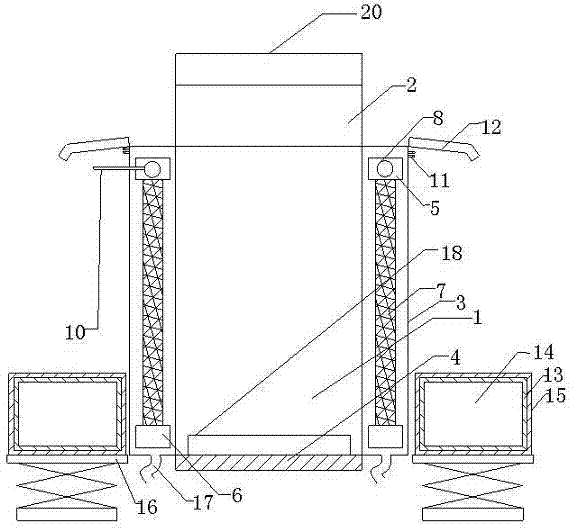
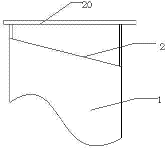
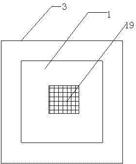
[0020] Such as Figure 1-3 As shown, the present invention is a dual-purpose anti-condensation switchgear for winter and summer. A protective cover layer 3 is provided on the outside of the switchgear 1. The protective cover layer 3 makes the switchgear and the external temperature a layer of isolation layer to avoid The large temperature difference forms condensed water inside and outside the switch cabinet. A moisture-proof partition layer 4 is arranged below the switch cabinet 1. The moisture-proof partition layer 4 can effectively prevent some influences caused by the direct contact between the switch cabinet and the ground. It is not only moisture-proof but al...


PUM


Abstract

The invention discloses an anti-condensation switch cabinet usable in summer and winter. A protection cover layer is arranged on the outer side of the switch cabinet, cooling heat insulation devices are arranged in a space formed by the switch cabinet and the protection cover layer and on the outer side, the front side, the rear side, the left side and the right side of the switch cabinet, each cooling heat insulation device comprises an upper aluminum alloy supporting frame and a lower aluminum alloy supporting frame, honeycomb wet curtain paper is arranged between the upper aluminum alloy supporting frame and the lower aluminum alloy supporting frame in each side, a water pipe with water leakage holes is inserted into each upper aluminum alloy supporting frame, water leakage holes are formed in each lower aluminum alloy supporting frame, and the water pipes are spliced together after the upper aluminum alloy supporting frame are placed into the switch cabinet. The anti-condensation switch cabinet is simple in structure and reasonable in design, condensation can be effectively prevented by the aid of the characteristics of natural environments and simple equipment, and safety of the switch cabinet is ensured.

Description

technical field [0001] The invention relates to the field of electric power technology, in particular to an anti-condensation switchgear for both winter and summer using natural conditions. Background technique [0002] The switchgear is a kind of electrical equipment. The external line of the switchgear first enters the main control switch in the cabinet, and then enters the sub-control switch. Each branch is set according to its needs. The equipment generates a lot of heat during operation. The temperature inside the switchgear is low and the temperature inside the switchgear is high. At this time, the temperature underground is higher than the temperature outside. At this time, the temperature at the bottom of the switchgear is not low. Concentrated on the top of the switch cabinet, if the heat is not dissipated in time, excessive heat will have a serious impact, but if the temperature of the upper part of the switch cabinet is too high, it will easily collide ...

Claims


Application Information

Patent Timeline
Patent Type & Authority Applications(China)
IPC IPC(8): H02B1/56
Inventor 蔡尚权
Owner STATE GRID CORP OF CHINA
Why Eureka
Try Eureka