Position detection device

A detection device and encoder technology, applied in valve devices, valve operation/release devices, valve details, etc., can solve problems such as inability to locate accuracy requirements, position misalignment, and valve damage to electric devices, and achieve extended position detection and reliability. Display time, improve equipment reliability, and ensure the effect of positioning accuracy

Active Publication Date: 2015-01-28
SHANGHAI YUANZHI INFORMATION TECH
View PDF4 Cites 6 Cited by
  • Summary
  • Abstract
  • Description
  • Claims
  • Application Information

AI Technical Summary

Problems solved by technology

Potentiometer detection uses a reduction gear set to convert multi-turn to single-turn, so when matching valves, the larger the diameter of the valve, the lower the detection accuracy of the valve position, which cannot meet the positioning accuracy requirements
The detection method of the Hall pulse relative to the encoder, because the counting pulse signal of the relative position is used, after the main power supply is lost, it is necessary to use a backup power supply or a battery to supply power to the encoder and processor, and to continuously record the Hall pulse signal. If the battery is dead or the pulse is lost, the detected valve position will be inaccurate, resulting in damage to the electric device or valve
The method of absolute value encoder is adopted, because the traditional absolute value encoder adopts the method of single-turn absolute value plus the method of recording the circle device, and the method of recording the number of revolutions is mostly used in the circle recording device. When there is a problem with the gears in the gear set, it will cause a large jump in the number of laps recorded by the lap recording device, resulting in misalignment or loss of position, resulting in failure

Method used


Image

  • Position detection device
  • Position detection device
  • Position detection device

Examples


Embodiment 2

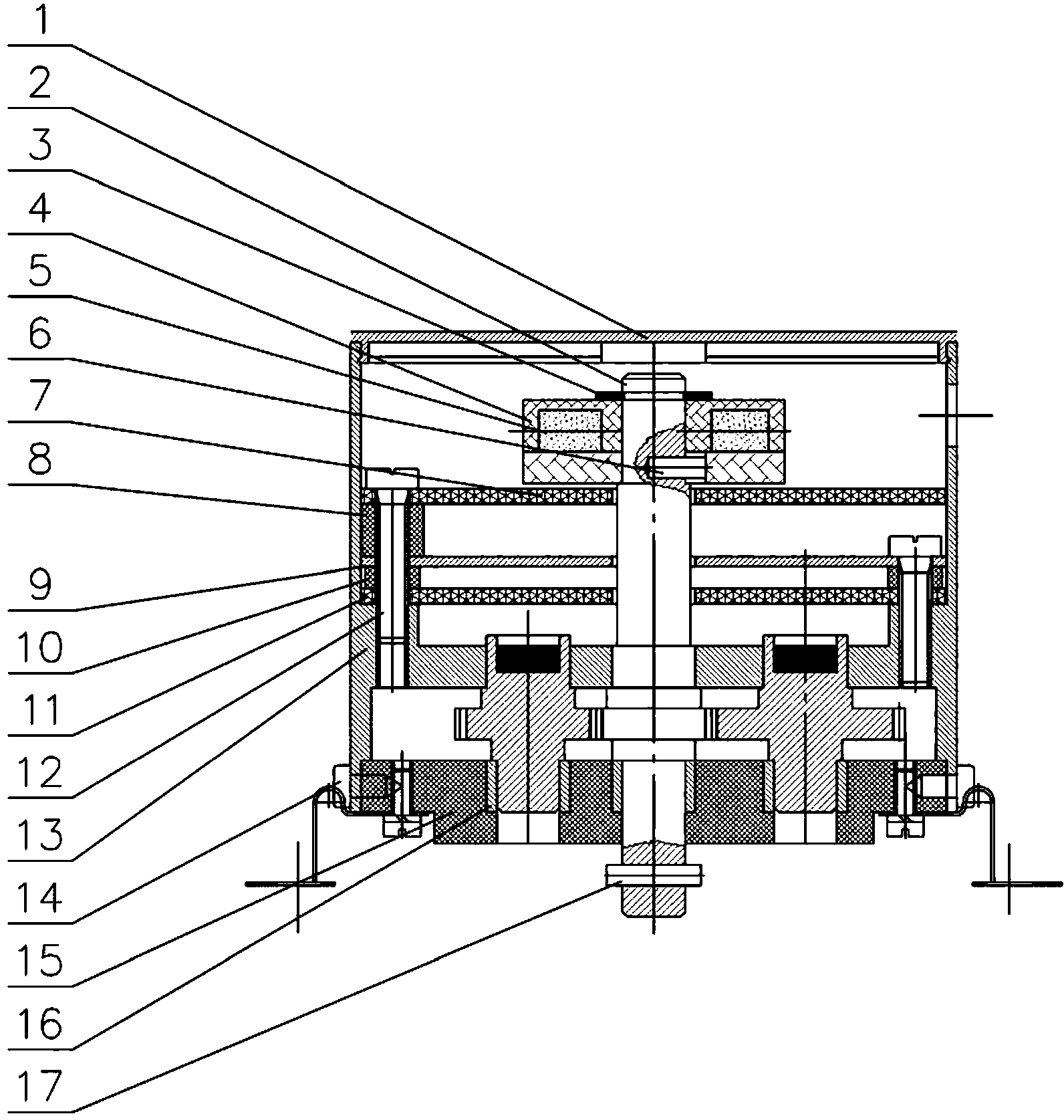
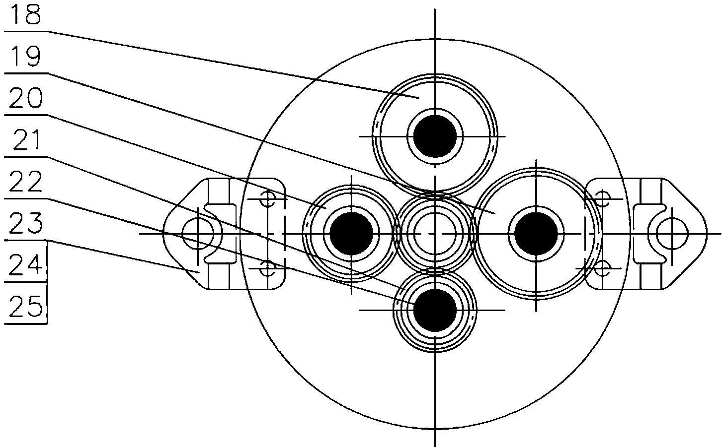
[0030] Embodiment 2: On the integration of the structure and circuit board layout of Embodiment 1, when the main control processor processes the data of the magnetic force line induction sensor and the magnetic pulse induction sensor, it adopts the position of collecting the two when the main power supply exists. The information is stored, and then the position information of the magnetic force line induction sensor is used as the main position information, and the information of the magnetic pulse induction sensor is used as auxiliary information. After the magnetic force line induction sensor fails, the information of the magnetic pulse induction sensor is automatically switched. When the main power supply does not exist, only the magnetic pulse induction sensor is collected for display and position judgment. After the main power supply is restored, the information of the magnetic force line induction sensor is used to calibrate the information of the magnetic pulse induction ...


PUM


Abstract

The invention discloses a position detection device. A magnetic force line inductive sensor and a magnetic pulse inductive sensor are simultaneously arranged in an encoder body. The magnetic force line inductive sensor comprises following gears different in tooth number and a magnetic force line inductive encoding circuit board. Iron-boron magnets are installed at the axis positions of the upper ends of the following gears. The magnetic pulse inductive sensor comprises an encoding disk body and a magnetic pulse inductive encoding circuit board, wherein six cylindrical neodymium iron boron magnets arranged at intervals of 60 degrees are installed in the encoding disk body. The position detection device adopts the magnetic force line position sensing system and the magnetic pulse position sensing system to detect a position signal of a valve electric device in the operation process and can obtain a real-time position of a valve, adjust actions of a motor in real time and ensure that an output shaft drives the valve and other objects to reliably and stably operate to designated valve positions. The problem of position detection accuracy is solved in a magnetic force line inductive mode, the power consumption problem of position detection is also solved in a magnetic pulse detection mode, and the positioning accuracy and reliability of the valve electric device are greatly improved.

Description

technical field [0001] The invention relates to the technical field of rotation position detection, in particular to a position detection device of a valve electric device. Background technique [0002] Intelligent valve electric devices are mainly used for fluid mechanical switching or adjusting positioning of valves and dampers, which are widely used in the process industry. The workplaces may be various, including environments with high requirements for explosion-proof and protection levels. The main control parameters of the intelligent valve electric device are position and torque. The accuracy of position detection determines the positioning accuracy of the valve opening, and the torque is mainly to protect the intelligent valve electric device and the valve from damage. To obtain the actual position of the valve electric device, it needs to be obtained through the position detection system of the intelligent valve electric device. [0003] At present, most of the pos...

Claims


Application Information

Patent Timeline
Patent Type & Authority Applications(China)
IPC IPC(8): F16K37/00F16K31/04
CPCF16K31/04F16K37/00
Inventor 叶嵩常守亮李彦樟
Owner SHANGHAI YUANZHI INFORMATION TECH
Why Eureka
Try Eureka