Linear Reluctance Motor

A reluctance motor and linear technology, applied in the direction of electrical components, electromechanical devices, electric components, etc., can solve the problems of high vibration and noise, large thrust fluctuation, low thrust density, etc., to reduce copper consumption, improve thrust density, and cost low effect

Active Publication Date: 2018-06-22
HARBIN INST OF TECH
View PDF5 Cites 0 Cited by
  • Summary
  • Abstract
  • Description
  • Claims
  • Application Information

AI Technical Summary

Problems solved by technology

[0006] The purpose of the present invention is to solve the problems of low thrust density, high winding copper consumption, large thrust fluctuation, high vibration and noise of the current linear switched reluctance motor. The present invention provides a linear reluctance motor

Method used


Image

  • Linear Reluctance Motor
  • Linear Reluctance Motor
  • Linear Reluctance Motor

Examples


specific Embodiment approach 1

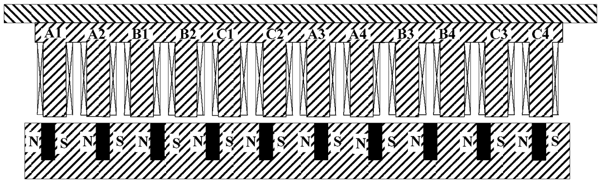
[0037] Specific implementation mode one: combine figure 1 Describe this embodiment, the linear reluctance motor described in this embodiment,

[0038] Including primary and secondary; there is an air gap between primary and secondary; the primary includes primary and secondary, and the primary includes primary core and primary winding; the primary core is in the shape of a flat plate, and the side of the air gap is grooved transversely to form 12 teeth , along the moving direction, a coil is wound on each tooth of the primary core, the primary winding is a 3-phase winding, a coil is wound on each tooth of the primary core, every two adjacent teeth and the upper The wound coils constitute a phase unit, and the winding directions of the coils on every adjacent two teeth of the two teeth forming a phase unit are opposite, and the two coils are connected in series; the whole motor has a total of 6 phase units, belonging to the same phase The phase unit coils are connected in ser...

specific Embodiment approach 2

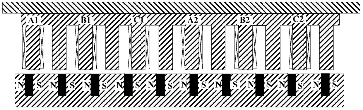
[0041] Specific implementation mode two: combination figure 2 Describe this embodiment, the linear reluctance motor described in this embodiment includes a primary and a secondary; there is an air gap between the primary and the secondary;

[0042] Primary includes primary core and primary winding;

[0043] The primary iron core is in the shape of a flat plate, and there are multiple slots on the side of the air gap in the transverse direction, and the formed teeth and slots are arranged alternately along the relative movement direction of the primary and secondary; along the movement direction, every other tooth in the primary iron core A coil is wound on the top, and the primary winding is a 3-phase winding, that is, the teeth with coils and the teeth without coils are arranged alternately along the moving direction, and each tooth and the coils wound on it constitute a phase unit;

[0044] The motor has three phase units in total, and the coils of the phase units belonging ...

specific Embodiment approach 3

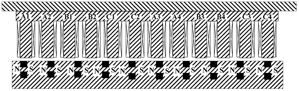
[0046] Specific embodiment three: the linear reluctance motor described in this embodiment,

[0047] The motor includes a primary and a secondary; there is an air gap between the primary and the secondary;

[0048] Primary includes primary core and primary winding;

[0049] The primary iron core is in the shape of a flat plate, and there are multiple slots along the transverse direction on the side of the air gap, and the formed teeth and slots are arranged alternately along the relative movement direction of the primary and secondary;

[0050] The number of secondary poles of the motor Z r with primary teeth number Z s satisfy the following relationship: Z s =mqZ r , q is the number of slots per pole and phase, and is a positive integer;

[0051] The primary winding is embedded in each slot, and the primary winding is a 3-phase symmetrical stacked winding;

[0052] The secondary includes a secondary iron core and a permanent magnet; the secondary iron core is in the sha...


PUM


Abstract

The invention discloses a linear reluctance motor, belongs to the field of motors and aims to solve the problems of low thrust density, high winding copper consumption, great thrust fluctuation and high vibration and noise of an existing linear switched reluctance motor. The linear reluctance motor comprises a primary linear reluctance motor, a secondary linear reluctance motor and an air gap which is formed between the primary linear reluctance motor and the secondary linear reluctance motor, wherein the primary linear reluctance motor comprises a primary iron core and a primary winding; grooves are horizontally formed in the air gap side of the primary iron core, and thus toothed grooves are sequentially arranged at intervals in the motion direction; the primary winding is a m-phase winding, and m is greater than or equal to 3; a coil is wound on each tooth of the primary iron core; each k adjacent teeth and coils which are wound on the teeth form a phase unit, k is greater than or equal to 2, and k coils are opposite in winding direction and are connected with one another together in series; m*n phase units belong to the same phase coil and are connected with one another together in series; the secondary linear reluctance motor comprises a secondary iron core and permanent magnets; grooves are horizontally formed in the air gap side of the secondary iron core and are uniformly arranged in the secondary iron core in the movement direction; a permanent magnet is placed in each groove and is magnetized; the permanent magnets of every two adjacent poles are opposite in magnetization direction. The technical scheme of the linear reluctance motor is applied to motors with high trust density and low motor copper consumption.

Description

technical field [0001] The invention belongs to the field of motors. Background technique [0002] The linear switched reluctance motor (Linear Switched Reluctance Motor, LSRM) is evolved from the traditional rotary switched reluctance motor (SRM). It is equivalent to unfolding the stator and rotor of the SRM along the circumferential direction, the rotor part corresponds to the secondary of the LSRM, and the stator part corresponds to the primary of the LSRM. Due to the limitations of the manufacturing process, the air gap between the primary and secondary stages of LSRM is generally larger than that between the stator and rotor of SRM. According to different applications, LSRM can adopt a moving primary or moving secondary structure. For LSRMs used for rail drives, the secondary length is generally much larger than the primary length. [0003] Figure 5 It is a schematic diagram of the structure of a three-phase 6 / 4 pole (primary pole number 6, secondary pole number 4) ...

Claims


Application Information

Patent Timeline
Patent Type & Authority Patents(China)
IPC IPC(8): H02K41/03
Inventor 寇宝泉贺铁锐牛旭谢逸轩邵一赵晓坤
Owner HARBIN INST OF TECH
Why Eureka
Try Eureka