Automatic punch

A punching machine and automatic technology, applied in the field of punching machines, can solve the problems of difficult punching accuracy, poor carrying capacity, time-consuming, etc., and achieve the effect of ensuring automatic production of equipment

Inactive Publication Date: 2015-04-01
袁瑞军
View PDF8 Cites 4 Cited by
  • Summary
  • Abstract
  • Description
  • Claims
  • Application Information

AI Technical Summary

Benefits of technology

This technology uses an angled rotation clamper for holding parts during manufacture or processing operations. It also has two types: a pneumatic tool used by programmers to create holes on products while they are being processed; and a machine called CNC (Computerized Numerically Controlled Computer) controlled machining tools to produce these tiny openings accurately through various methods like drilling or milling processes. These technical improvements make this process more efficient than traditional manual techniques such as cutting or sand blasting.

Problems solved by technology

This technical problem addressed by this patented technology relates to improving upon existing methods for machining holes into pipelines or other materials such as metal plating without sacrificially increasing their strength due to being supported from an anchor point at different locations within the material's structure.

Method used


Image

  • Automatic punch
  • Automatic punch
  • Automatic punch

Examples


Embodiment Construction

[0018] Embodiments of the present invention will be further described below in conjunction with accompanying drawings:

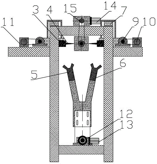
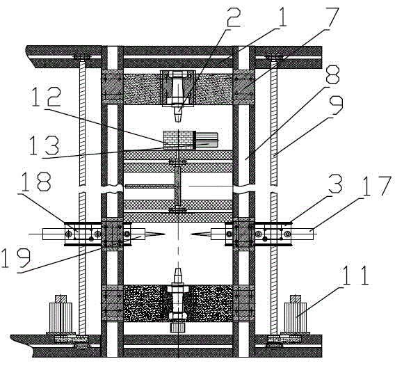
[0019] Such as figure 1 with figure 2 As shown, the present invention provides an automatic punching machine, which includes a body 1, a clamping device that swings laterally is provided on the base of the body 1, and a rotatable working clamping device is provided on the upper end of the body. The working clamping device has a first position for clamping the product and a second position for releasing the clamped product. Both sides of the working clamping device are provided with a punching mechanism that can move parallel to and perpendicular to the product. The clamping The holding device includes a feed air claw 5 and a discharge air claw 6, the feed air claw 5 has a first position for clamping unprocessed products and a second position for swinging and installing unprocessed products on the working clamping device, The discharge air claw 6 has a fir...


PUM


Abstract

The invention relates to an automatic punch which comprises a body, wherein a transversely rotating clamping device is arranged on a base of the body. A rotatable work butting device is arranged at the upper end of the body and is provided with a first position for butting clamped products and a second position for loosening clamped products. Punching mechanisms capable of moving parallel to or perpendicular to products are arranged on two sides of the work butting device. The clamping device comprises a material inlet pneumatic gripper and a material outlet pneumatic gripper. The material inlet pneumatic gripper is provided with a first position for gripping unprocessed products and a second position which rotates to arrange the unprocessed products on a work clamping device. The material outlet pneumatic gripper is provided with a first position for clamping processed products from the work clamping device and a second position which rotates to discharge processed products. The angle rotating clamping device is adopted to conduct material inlet and outlet clamping, the punching mechanism capable of moving parallel to or perpendicular to products are matched with the rotatable work butting device, accordingly requirements of one-time multiple hole sites and multiple hole shapes punching are met, and automatic device production is ensured.

Description


Claims


Application Information

Patent Timeline
Owner 袁瑞军
Why Eureka
Try Eureka