
Motor base inner hole machining equipment

A technology for processing equipment and motor bases, which is applied to metal processing equipment, metal processing machinery parts, manufacturing tools, etc., can solve the problems of time-consuming and labor-intensive drilling of motor bases, health hazards of workers, etc., and achieve the effect of preventing blockage

Inactive Publication Date: 2020-11-10
缪新建
View PDF8 Cites 4 Cited by
  • Summary
  • Abstract
  • Description
  • Claims
  • Application Information

AI Technical Summary

Problems solved by technology

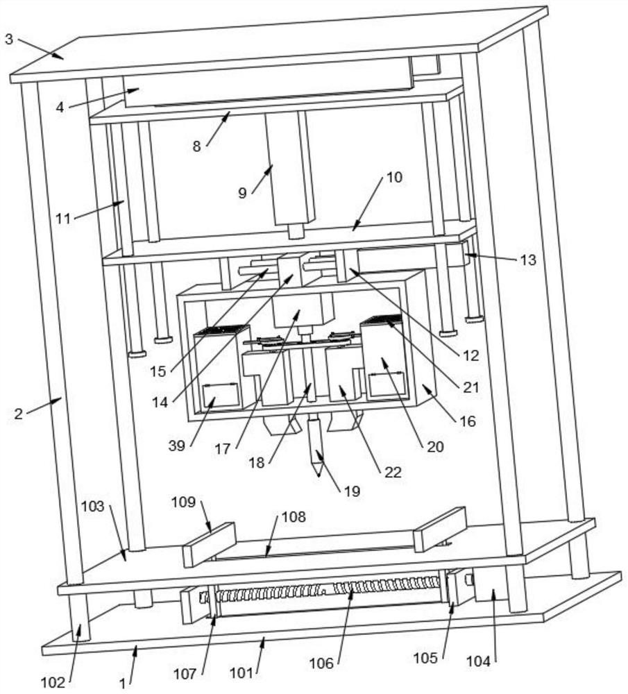
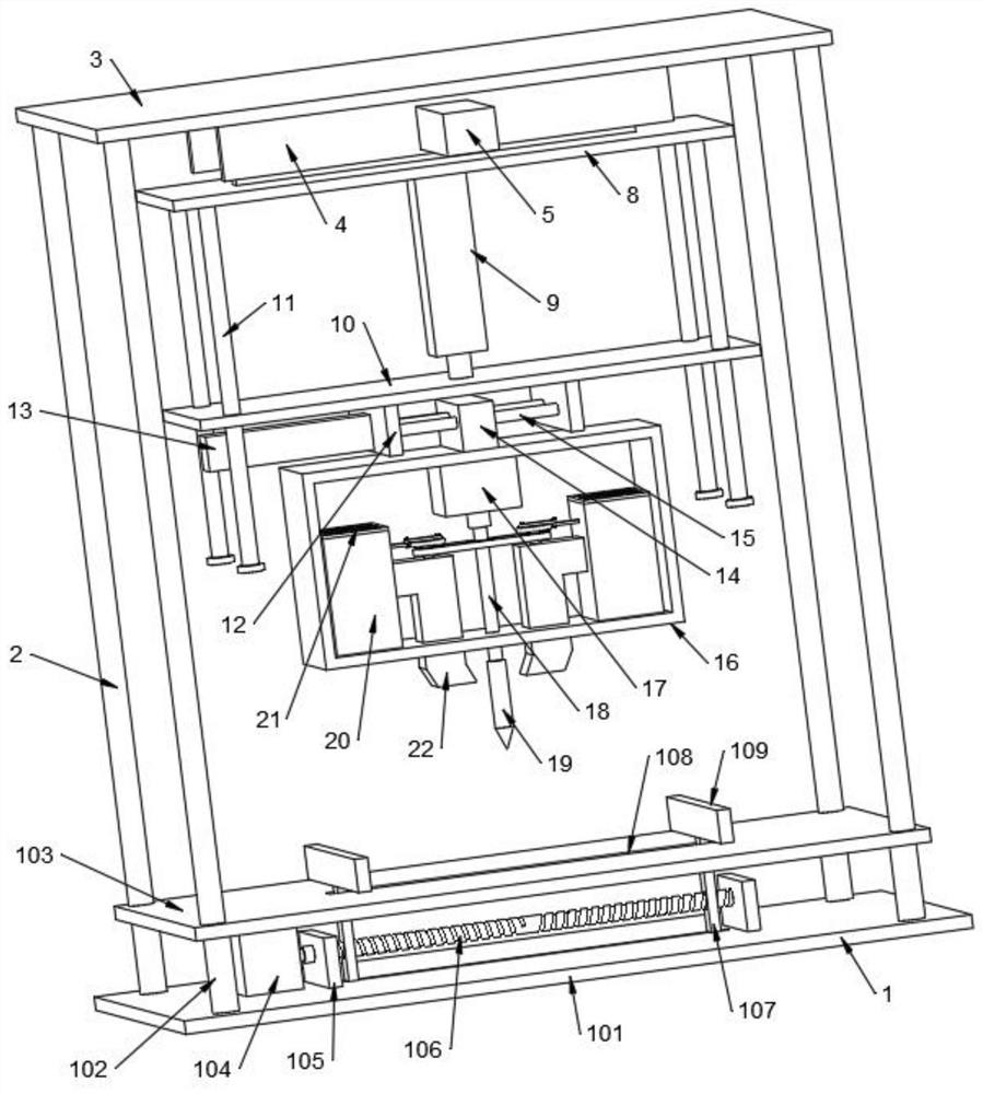
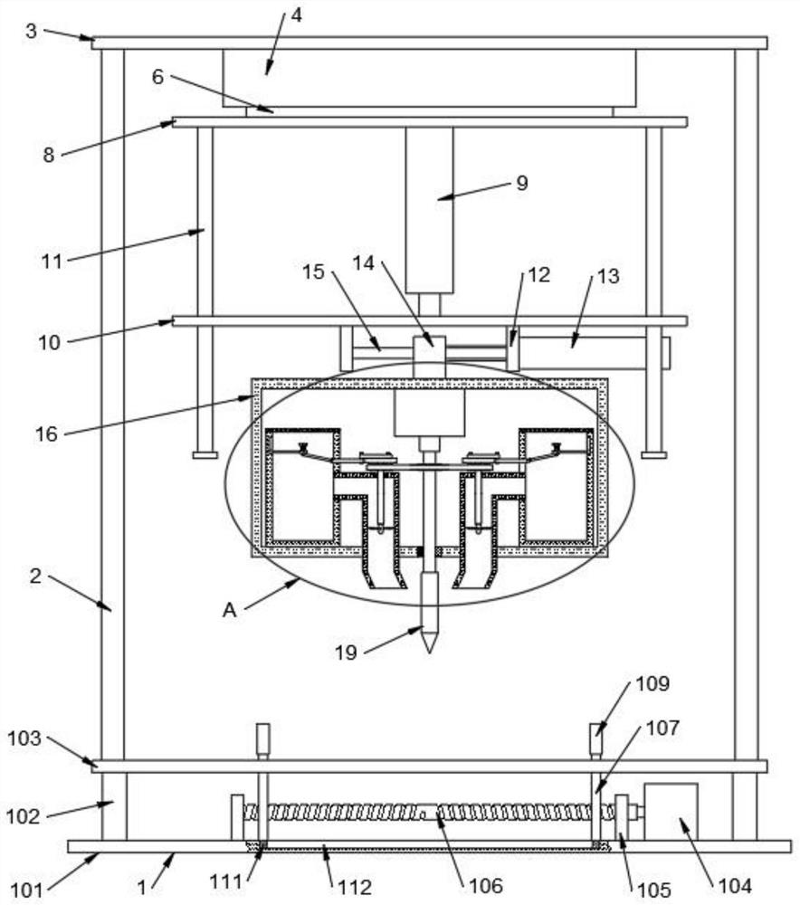
[0004] The purpose of the present invention is to solve the problem in the prior art that it is time-consuming and labor-intensive to punch holes in the motor base, and will generate a large amount of dust, which will cause great harm to the health of workers, and proposes a motor base inner hole processing equipment

Method used


Image

  • Motor base inner hole machining equipment
  • Motor base inner hole machining equipment
  • Motor base inner hole machining equipment

Examples


Embodiment Construction

[0033] The following will clearly and completely describe the technical solutions in the embodiments of the present invention with reference to the accompanying drawings in the embodiments of the present invention. Obviously, the described embodiments are only some, not all, embodiments of the present invention.

[0034] In describing the present invention, it should be understood that the terms "upper", "lower", "front", "rear", "left", "right", "top", "bottom", "inner", " The orientation or positional relationship indicated by "outside", etc. is based on the orientation or positional relationship shown in the drawings, and is only for the convenience of describing the present invention and simplifying the description, rather than indicating or implying that the referred device or element must have a specific orientation, so as to Specific orientation configurations and operations, therefore, are not to be construed as limitations on the invention.

[0035] refer to Figure 1-...


PUM


Abstract

The invention discloses motor base inner hole machining equipment, and belongs to the technical field of motor base machining equipment. The motor base inner hole machining equipment comprises a clamping device, four stand columns are symmetrically arranged at the top of the clamping device, a top plate is fixed to the tops of the four stand columns, and vertical plates are symmetrically fixed tothe bottom of the top plate, wherein a first electric push rod is fixed to one side wall of one vertical plate; and the output end of the first electric push rod penetrates through one side wall of the adjacent vertical plate and is fixedly provided with a first connecting plate, and first guide rods are symmetrically arranged below the top plate. According to the motor base inner hole machining equipment, a motor base can be relatively conveniently and rapidly fixed, and front-back movement, up-down movement and left-right movement of a drill bit can be achieved, so that the punching requirement for the motor base can be met, generated dust can be sucked into a box body in the punching process, and the situation that meshes of a stainless steel filter screen plate are blocked can be prevented.

Description

technical field [0001] The invention relates to the technical field of motor seat processing equipment, in particular to a motor seat inner hole processing device. Background technique [0002] With the rapid development of the national economy and the revitalization of basic industries, the motor manufacturing industry has made great progress. New motors continue to introduce new ones and become market-leading. More manufacturers have begun to participate in the manufacture of medium and large motors. It is undoubtedly the most important part. The motor base needs to be drilled during the processing process, so drilling equipment is required. [0003] At present, the motor base is generally drilled by the worker's hand-held electric drill, so the operation is time-consuming and laborious, and a large amount of dust will be generated when drilling, which will cause great harm to the health of the staff. Therefore, we propose a machine for processing the inner hole of the mo...

Claims


Application Information

Patent Timeline
Patent Type & Authority Applications(China)
IPC IPC(8): B23Q3/06B23Q5/28B23Q11/00
CPCB23Q3/062B23Q5/28B23Q11/00B23Q11/0042B23Q11/0046
Inventor 缪新建
Owner 缪新建
Learn More