
Reversing radar punching equipment special for automobile rear bumper

A reversing radar and bumper technology, applied in metal processing and other directions, can solve the problems of difficulty in improving product productivity, lack of rear bumper reversing radar installation holes, affecting product surface quality, etc., to improve production efficiency, equipment structure is reasonable and beautiful, Place easy effects

Inactive Publication Date: 2015-05-20
LIUZHOU ZHENGYUAN ELECTROMECHANICAL
View PDF6 Cites 5 Cited by
  • Summary
  • Abstract
  • Description
  • Claims
  • Application Information

AI Technical Summary

Problems solved by technology

If you want to realize the opening of the reversing radar installation hole on the mold, there will be many unnecessary core-pulling mechanisms on the mold, which will affect the surface quality of the product, and it is difficult to improve the productivity of the product
At present, there is no punching device specifically for the mounting hole of the rear bumper reversing radar, let alone the punching device for the mounting hole of the rear bumper of the Wuling Baojun model.

Method used


Image

  • Reversing radar punching equipment special for automobile rear bumper
  • Reversing radar punching equipment special for automobile rear bumper
  • Reversing radar punching equipment special for automobile rear bumper

Examples


Embodiment 1

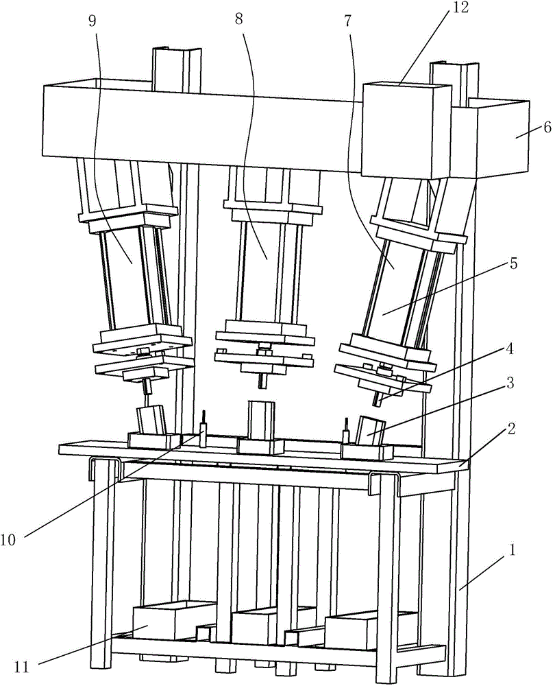
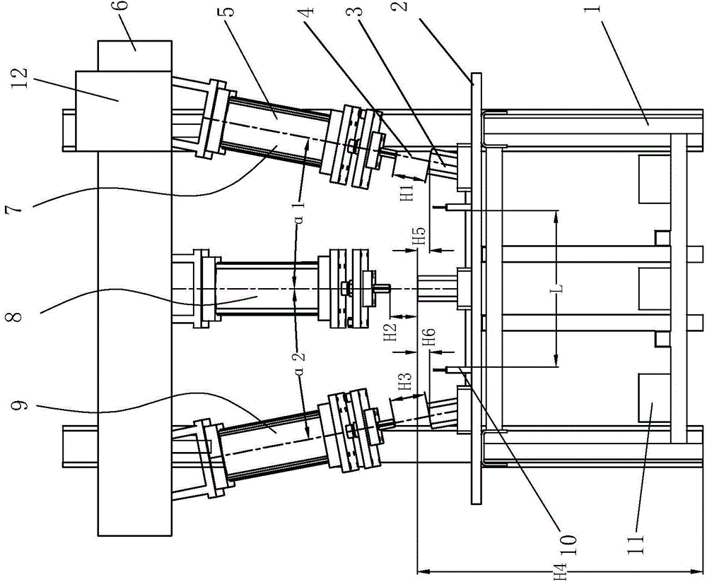
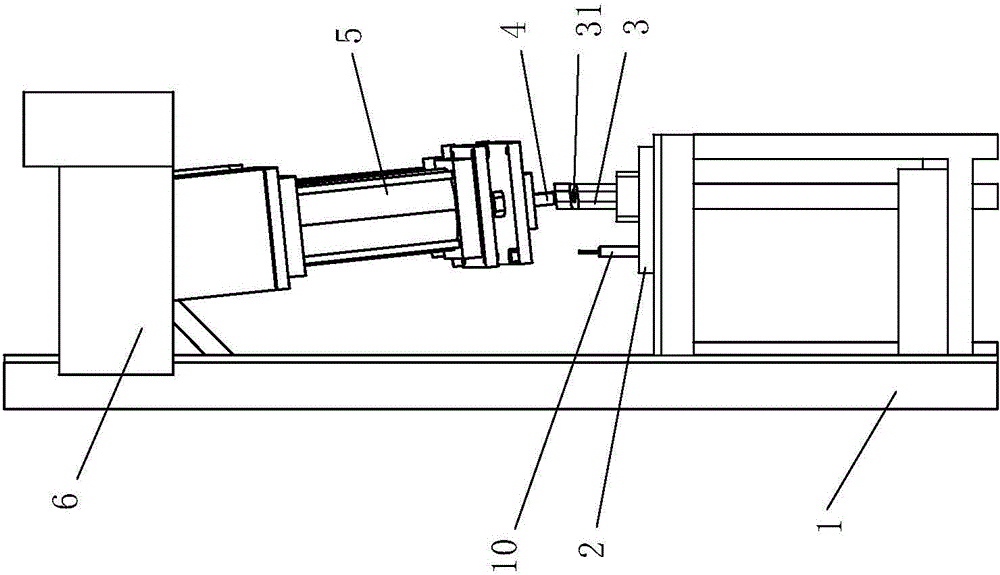
[0026] Embodiment 1: A special reversing radar punching device for the rear bumper of an automobile, such as Figure 1-Figure 3 As shown, it includes a frame 1, a bumper positioning device 10, a punching assembly I7, a punching assembly II8, and a punching assembly III9. The frame is provided with a cylinder mounting plate 6 and a tire mold mounting plate 2 respectively. The punching assembly I, punching assembly II, and punching assembly III described above are all composed of a bumper imitation tire mold 3 installed on the tire mold mounting plate, a stamping cylinder 5 connected to the cylinder mounting plate, and a punching cylinder mounted on the stamping cylinder. The punching knife 4 on the upper part is composed of a punching hole 31 matched with the punching knife in the middle of the bumper profiling tire mold, and the bumper profiling tire mold 3, stamping cylinder 5 and punching of the same group of punching components are The center line of the knife 4 is located o...


PUM


Abstract

The invention relates to reversing radar punching equipment special for an automobile rear bumper. The reversing radar punching equipment comprises a rack, a bumper positioning device, a punching assembly I, a punching assembly II and a punching assembly III. The rack is provided with an air cylinder mounting plate and a forming die mounting plate. The punching assembly I, the punching assembly II and the punching assembly III are each composed of a bumper profiling forming die arranged on the forming die mounting plate, a punching air cylinder connected to the air cylinder mounting plate and a punching knife arranged on the punching air cylinder. The middles of the bumper profiling forming dies are provided with punched holes matched with the punching knifes. The end faces of the bumper profiling forming dies are circular-arc faces. The bumper positioning device is composed of two positioning pins. The reversing radar punching equipment has the advantages that the equipment is high in positioning accuracy, free of influences on product surface quality, high in production efficiency and the like, and the punching quality meets the assembling requirement of reversing radar.

Description

technical field [0001] The invention relates to a punching device, in particular to a special reversing radar punching device for the rear bumper of an automobile. Background technique [0002] According to the market needs of the current car bumper configuration, the rear bumper is divided into two configurations: low configuration and high configuration. The bumper with high configuration needs to open the installation hole for installing the reversing radar, while the bumper with low configuration does not need to open the installation hole. If the mounting holes for the reversing radar are to be opened on the mold, there will be many unnecessary core-pulling mechanisms on the mold, which will affect the surface quality of the product, and it will be difficult to improve the productivity of the product. At present, there is no punching device specifically for the mounting hole of the rear bumper reversing radar, let alone the punching device for the mounting hole of the ...

Claims


Application Information

Patent Timeline
Patent Type & Authority Applications(China)
IPC IPC(8): B26F1/04B26F1/14B26D7/01
CPCB26F1/04B26D7/01B26F1/14
Inventor 徐宣文麻民思徐宏光
Owner LIUZHOU ZHENGYUAN ELECTROMECHANICAL
Learn More