Rotary tool, in particular drill

A technology of rotating cutters and drills, which is applied to milling cutters, reamers, twist drills, etc. It can solve problems such as high thermal load, high mechanical load, and increased burrs, and achieve simple geometry, avoid burrs, and simple production

Active Publication Date: 2010-09-01
KENNAMETAL INC
View PDF1 Cites 15 Cited by
  • Summary
  • Abstract
  • Description
  • Claims
  • Application Information

AI Technical Summary

Problems solved by technology

[0003] For example, during cutting operations with drills, but also by reamers, milling cutters, especially end mills, step drills, deep hole drills or "side-and-side cutters", it is often a problem that these rotating tools Simultaneously high mechanical and thermal loads for medium cutting corners
However, at the same time, there is a problem that when forming a through opening (such as a through hole), the unwanted burr at the exit of the drilled hole increases.

Method used


Image

  • Rotary tool, in particular drill
  • Rotary tool, in particular drill
  • Rotary tool, in particular drill

Examples


Embodiment Construction

[0026] Parts having the same effect in the figures are provided with the same reference symbols.

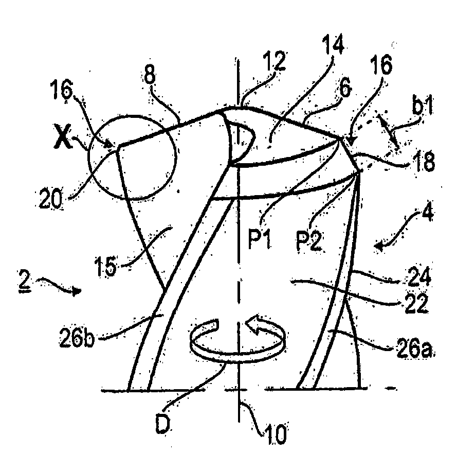
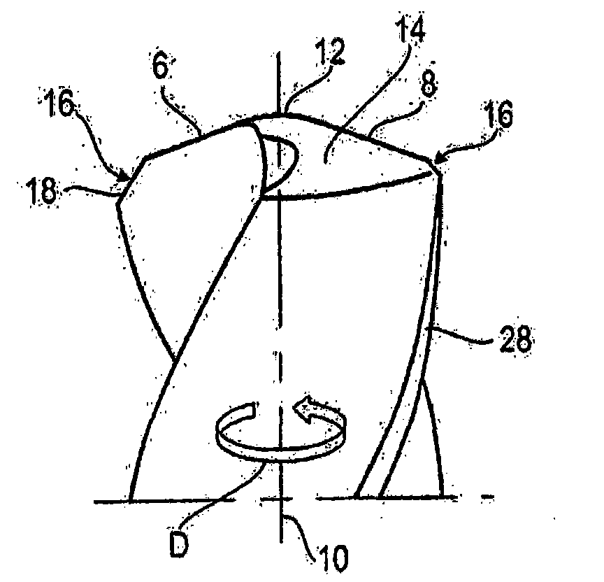
[0027]These individual details and features are illustrated below with reference to a rotary tool designed as a twist drill 2 . The only partially shown twist drill 2 has a drill point 4 as a cutting head, on which a plurality of main cutting edges 6, 8 (two in the exemplary embodiment) are formed at the end face . In the following, one main cutting edge is called leading cutting edge 6 and the other main cutting edge is called free cutting edge 8 . The two main cutting edges 6 , 8 are connected to one another by a chisel edge 12 in the region of a central axis of the drill 2 which simultaneously forms an axis of rotation 10 . During use, the drill bit 2 is rotated in a direction of rotation D about a drill central axis 10 . The drill point 4 is substantially designed in the shape of a conical side surface, so that the main cutting edges 6 , 8 extend obliquely outward from the...


PUM


Abstract

In order to provide a rotary tool, in particular a drill (2), with a long service life together with high-quality drill holes, particularly in the case of through bores, the invention provides a cutting head (4) which extends along a rotational axis (10) and has a plurality of main cutting edges (6, 8) which extend radially outwards and each end at a cutting corner (16) having a corner bevel, wherein the corner bevels are of differing designs, specifically in the form of a roughing bevel (18) and in the form of a finishing bevel (20).

Description

technical field [0001] The invention relates to a rotary tool, in particular a drill comprising a cutting head extending along an axis of rotation and having a plurality of main cutting edges extending radially outwards and Each tip has a corner bevel at a cutting corner at the circumference of the cutting head. Background technique [0002] Such a cutting tool designed as a rotary tool is known, for example, from DE 20209767 U1. [0003] For example, during cutting operations with drills, but also by reamers, milling cutters, especially end mills, step drills, deep hole drills or "side-and-side cutters", it is often a problem that these rotating tools Medium cutting corners are subjected to high mechanical and thermal loads at the same time. In order to reduce this load, it is known to provide "corner bevels" at the cutting corners. Due to this corner bevel, the main cutting edge does not extend straight over the circumference. Consequently, no cutting corners with shar...

Claims


Application Information

Patent Timeline
Patent Type & Authority Applications(China)
IPC IPC(8): B23B51/02
CPCB23C2210/325B23B2251/282B23B2251/44B23D77/00B23B2220/24B23C2210/54B23C5/10B23B2220/44B23B51/02B23B2251/14B23C2220/605B23B2251/248Y10T408/9097Y10T408/909Y10T408/906
Inventor H·R·考佩尔
Owner KENNAMETAL INC
Why Eureka
Try Eureka