Method for positioning position of high-speed parallel data flow trigger point

A technology of data flow and trigger point, applied in the direction of analog/digital conversion, digital variable display, signal transmission system, etc., can solve the problem of not simplifying the logic of synchronous processing, and achieve the effect of low cost

Active Publication Date: 2015-04-08
BEIJING AEROSPACE MEASUREMENT & CONTROL TECH
View PDF6 Cites 1 Cited by
  • Summary
  • Abstract
  • Description
  • Claims
  • Application Information

AI Technical Summary

Problems solved by technology

Although this method simplifies the trigger channel circuit, it still requires an additional voltage comparison circuit, and does not simplify the complex synchronization processing logic, and there are still errors

Method used


Image

  • Method for positioning position of high-speed parallel data flow trigger point
  • Method for positioning position of high-speed parallel data flow trigger point
  • Method for positioning position of high-speed parallel data flow trigger point

Examples


Embodiment Construction

[0021] The present invention will be further described below in conjunction with the accompanying drawings.

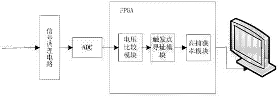
[0022] A method for locating the position of the trigger point of the high-speed parallel data stream of the present invention, the specific implementation includes a digitized voltage comparator and a pipeline trigger addressing module, all of which are completed inside the FPGA.

[0023] like figure 1 As shown, the analog signal is transformed into a digital signal after being converted by the ADC, and the digital signal is sent to the FPGA for serial-to-parallel conversion to become a parallel data stream. Under the digital clock, there are several sampling points to be processed in each cycle, and the trigger can be found quickly and accurately. The position includes two aspects, one is to determine that the data point where the trigger occurs is located in a certain period of the parallel data stream, and the other is to determine which point in the parallel data ...


PUM


Abstract

The invention provides a method for positioning the position of a high-speed parallel data flow trigger point; the position of the trigger point can be directly used, so that a digital three-dimensional oscilloscope is realized. The method comprises the following steps of (1) comparing parallel data with the upper limit and the lower limit of a trigger zone to obtain two paths of parallel comparison results; (2) dividing LData into a plurality of groups, implementing bitwise OR on first-order grouped data, determining whether a first bit of which the value is one occurs or not in the group, and determining the position of the first bit of which the value is one; (3) grouping data which are obtained after the implementation of bitwise OR on the first-order grouped data, and finding the position of the first bit of which the value is one by using the method of the step two till the position of the first bit of which the value is one in the LData can be determined; (4) after finding the positions of the bit of which the value is one, generating a corresponding data mask LDataMask; (5) implementing AND operation on the data mask LDataMask and HData to obtain a data mask HDataMask; (6) finding the position of the first bit of which the value is one about the data mask HDataMask, i.e. the position of the trigger point in the data flow, according to the methods of the step two and the step three.

Description

technical field [0001] The invention relates to the field of digital storage oscilloscope data sampling triggering, in particular to a method for locating the trigger point position of high-speed parallel data streams, which is used to improve the stability of waveform display. Background technique [0002] The high-speed digital oscilloscope quantifies and samples the analog signal through a high-speed analog-to-digital converter (ADC), sends the data to the field programmable logic gate array (FPGA) for processing, and stores it in the memory. When displaying, the data is read from the memory and sent to the The display shows. With the continuous development of electronic technology, the sampling rate of the oscilloscope is required to reach several GHz to tens of GHz, but FPGA is far from reaching such a high processing speed, so the sampled data needs to be processed in parallel. Multiple parallel data streams bring challenges to high-speed data acquisition trigger syst...

Claims


Application Information

Patent Timeline
Patent Type & Authority Applications(China)
IPC IPC(8): H03M1/54G01R13/02
Inventor 林桐刘家玮胡志臣储艳丽张晓
Owner BEIJING AEROSPACE MEASUREMENT & CONTROL TECH
Why Eureka
Try Eureka