Check patentability & draft patents in minutes with Patsnap Eureka AI!

An integrated distribution frame

A distribution frame and rack technology, applied in the field of integrated distribution frames, can solve the problems of inconvenient installation of LED lights, troublesome direction adjustment, high processing defective rate, etc., and meet the requirements of line transformation and change, convenient operation, and practical structure Effect

Active Publication Date: 2017-09-29
NINGBO LINGTONG TELECOM EQUIP
View PDF5 Cites 0 Cited by
  • Summary
  • Abstract
  • Description
  • Claims
  • Application Information

AI Technical Summary

Problems solved by technology

[0002] The distribution frame is widely used in optical fiber fusion splicing, wiring, scheduling, and testing optical communication terminal equipment between optical fiber access network cables. It is the hub of signal transmission, scheduling, and replacement between optical signal transceiver equipment. Scheduling, switching and other functions, according to different network distribution methods, people have developed a variety of optical fiber distribution frames, common optical fiber distribution frames are mostly single-sided operation structures, and a small number of double-sided operations are used in the market The optical fiber distribution frame is also limited to the terminal on one side, and the other side is only for the routing management of the optical fiber. Now there are in-line modules and horizontal modules in the distribution frame, sockets are set on the modules, and the upper side walls of the modules Placement grooves are arranged on both sides, and LED display lights are arranged in the placement grooves. The LED display lights are used for the user to confirm the connection status of the optical cable connection, but the upper part of the module is very thin, so the space for the installation grooves is limited. , resulting in the installation of LED lights is very inconvenient, and the processing defective rate is high
In addition, after the current optical distribution frame is installed and fixed, the position is determined, and it is very troublesome to move or adjust the direction

Method used


Image

  • An integrated distribution frame
  • An integrated distribution frame
  • An integrated distribution frame

Examples


Embodiment Construction

[0016] The present invention will be further described in detail below in conjunction with the accompanying drawings and specific embodiments.

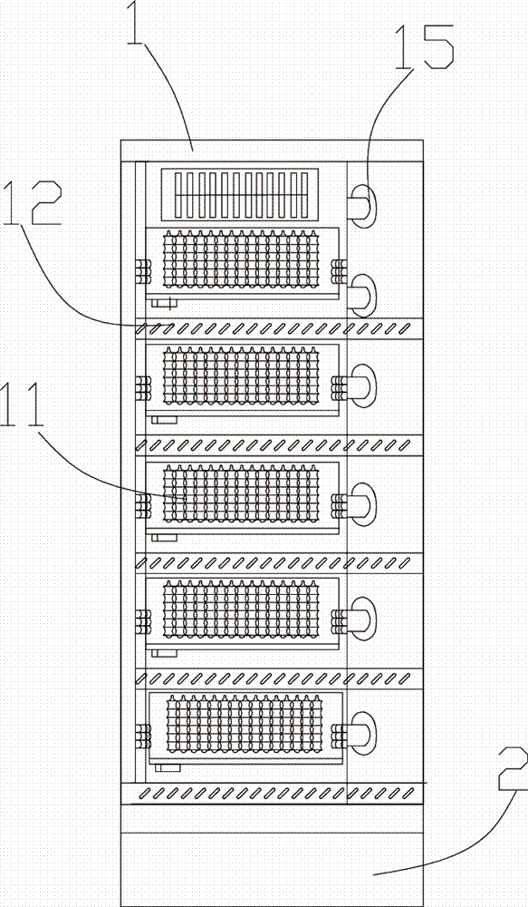
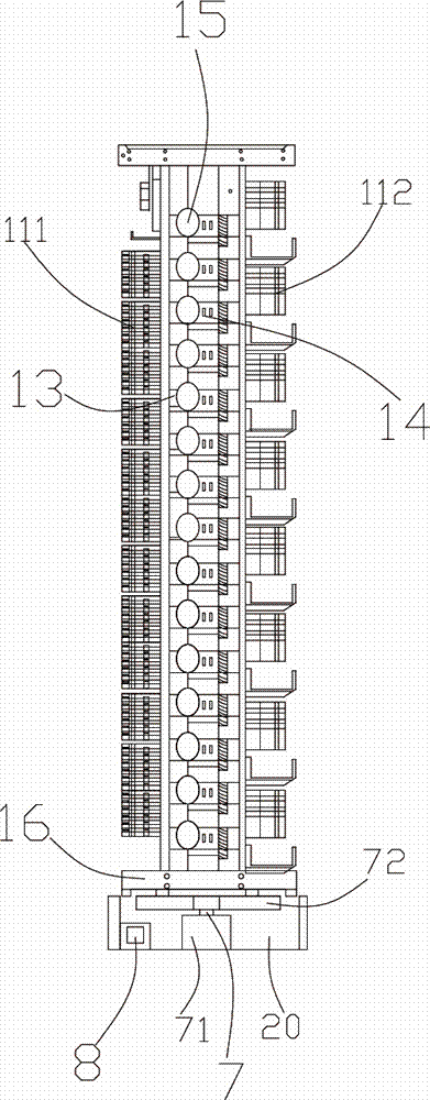
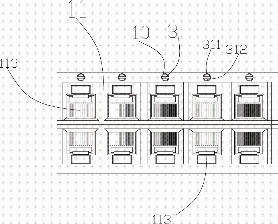
[0017] see figure 1 to Figure 6 As shown, an integrated distribution frame includes a rack 1, and a module 11 is arranged on the rack 1, and the module 11 includes an in-line module 111 and a row module 112, and the in-line module 111 and the row module 112 are respectively arranged on the front and back surfaces of the rack 1, the row modules 112 include multi-layer row rows composed of 96-core terminal panels, and horizontal wiring grooves 12 are arranged under each row row, and the row module 111 is It consists of multiple 72-core integrated machine frames arranged vertically. An optical cable fixing plate 13 is arranged on the side of the rack 1. The optical cable fixing plate 13 is located at the upper or lower end of the in-line module 111. Its features That is, a wire loop 14 and a fiber hanging wheel 15 are arranged on the...


PUM


Abstract

The invention discloses a comprehensive distribution frame and belongs to the technical field of optical fiber wiring. The distribution frame comprises a rack, wherein modules are arranged on the rack; a tray is arranged at the lower end of the rack; a fixing seat is arranged at the lower end of the tray; a rotating mechanism is arranged in the fixing seat; sockets are arranged in the modules; light guide bars are arranged above the sockets and are divided into front light guide bars and rear light guide bars; second through holes are formed in the rear light guide bars in parallel; C part light guide bars are arranged in the second through holes; and air bags are arranged at the tail ends of the C part light guide bars. Compared with the prior art, the distribution frame can be moved and an angle of the distribution frame can be adjusted according to practical requirements; the distribution frame meets requirements of line transformation, transition and the like; lamp bulbs are arranged at the rear ends of the modules on the distribution frame; light rays of the lightened lamp bulbs illuminate the rear light guide bars to lighten the front light guide bars to allow a user to confirm a connection state during connection; and the distribution frame is simple in structure, convenient and practical.

Description

technical field [0001] The invention belongs to the technical field of optical fiber distribution, in particular to an integrated distribution frame. Background technique [0002] The distribution frame is widely used in optical fiber fusion splicing, wiring, scheduling, and testing optical communication terminal equipment between optical fiber access network cables. It is the hub of signal transmission, scheduling, and replacement between optical signal transceiver equipment. Scheduling, switching and other functions, according to different network distribution methods, people have developed a variety of optical fiber distribution frames, common optical fiber distribution frames are mostly single-sided operation structures, and a small number of double-sided operations are used in the market The optical fiber distribution frame is also limited to the terminal on one side, and the other side is only for the routing management of the optical fiber. Now there are in-line modul...

Claims


Application Information

Patent Timeline
Patent Type & Authority Patents(China)
IPC IPC(8): G02B6/44
CPCF21V19/001F21V23/06G02B6/4452
Inventor 邓奕丁高文雄林辉宣沈金标
Owner NINGBO LINGTONG TELECOM EQUIP
Features
  • R&D
  • Intellectual Property
  • Life Sciences
  • Materials
  • Tech Scout
  • Unparalleled Data Quality
  • Higher Quality Content
  • 60% Fewer Hallucinations
Learn More