Bathroom master control switch

A technology for controlling switches and switches, applied in the direction of electrical switches, contacts, electrical components, etc., can solve the problems of inconvenient operation, loose wiring, weak connection, misconnection, etc., to improve the ability to pass current, and the overall structure is reasonable and practical. , The effect of easy production and assembly

Inactive Publication Date: 2015-04-15
许全忠
View PDF4 Cites 6 Cited by
  • Summary
  • Abstract
  • Description
  • Claims
  • Application Information

AI Technical Summary

Problems solved by technology

Metal connectors are used as wires in the switch and connected to each switch to avoid the defects caused by the separate establishment of the previous switch or the use of wires to connect, such as easy to cause problems such as loose wiring, infirmity, and misconnection, which improves the safety of the switch. Safety, at the same time, the structure is relatively simple, easy to manufacture, and the advantages of low cost. It can be further improved in practice. For example, there are usually 2 side-by-side switches in the Yuba control switch to control 2 sets of heating devices such as heating bulbs. Or electric heating tube, the connection of its switch is as follows Figure 7 As shown, the defect is that the current on the loop line is too large, and it is easy to burn the Yuba switch. In addition, it is necessary to control the operation of the heating device after the switching part of the hair dryer is connected. Therefore, it is inconvenient to operate and needs to be improved.

Method used


Image

  • Bathroom master control switch
  • Bathroom master control switch
  • Bathroom master control switch

Examples


Embodiment Construction

[0024] The present invention will be further described in detail below in conjunction with the accompanying drawings and embodiments.

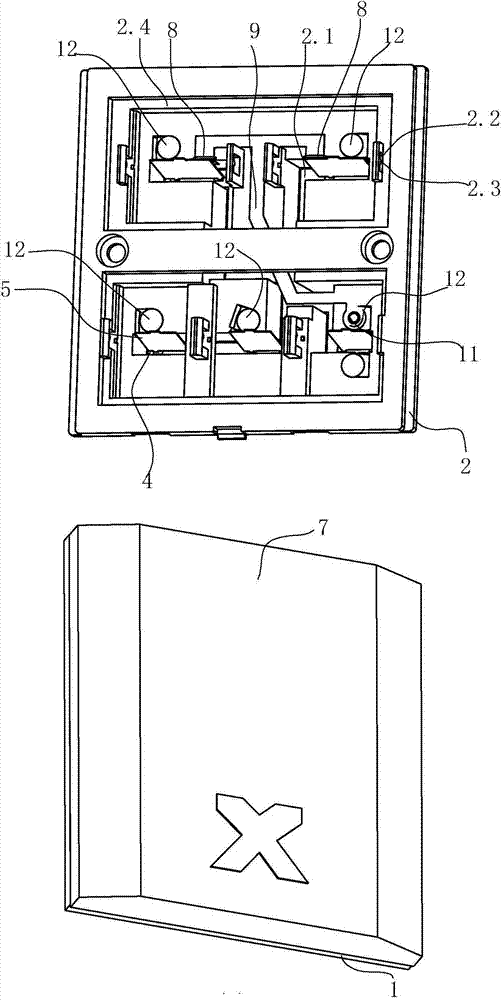
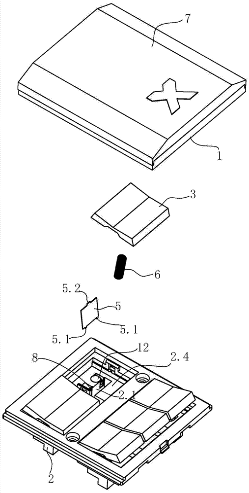
[0025] Such as Figure 1-6 As shown, a Yuba control switch includes main components such as a panel 1, a switch base 2, a switch press plate 3, a metal connector 4, a metal springboard 5, a spring 6, and a cover plate 7, among which the switch base 2 is uniform There are five cavities 2.1 for accommodating switch parts, usually two cavities in the upper row and three cavities in the lower row, and the cavities 2.1 are connected, and the size of a metal connector 4 is the same as The shape of the cavity is matched, the metal connector 4 is laid flat on the bottom of the cavity, and the intermediate connecting column is set in the middle of the metal connector 4, preferably in the center, of course, it can also be arranged eccentrically, not on the metal connector At the center position, the metal connecting piece 4 is connected to the input po...


PUM


Abstract

A bathroom master control switch comprises a panel, a switch base and a switch pressing board. The switch base is internally provided with a plurality of cavities for arranging switch members. The cavities are communicated so that a metal connecting member can be paved on the bottom of each chamber, and the metal connecting member is connected with an input power line through an intermediate connecting column. The metal connecting member is rotatably provided with a metal springboard on the bottom of each cavity. The upper end of each metal springboard is matched with a middle opening of the switch press board, and supports a spring. A metal connecting column is fixed to a side of each cavity, and a wiring hole for being connected with an output power line is arranged below each metal connecting column. Moreover, the contact surfaces of each metal springboard and the corresponding metal connecting column are provided with matching contacts. The bathroom master control switch is characterized in that a metal contact piece for electrical conduction is arranged near the opening of each cavity of the switch base and beside the corresponding metal connecting column for connecting heating devices, each metal contact piece is matched with the metal connecting column beside the metal contact piece, each metal contact piece contacts the corresponding metal springboard to conduct electricity or be separated from the metal springboard, and each metal contact piece and at least one metal connecting column for connecting non-heating devices are connected by a metal connecting piece. The bathroom master control switch of the invention is reasonable in structure and practical, has better current-through performance, and can be protected from burnout.

Description

technical field [0001] The invention relates to the technical field of a switch. Background technique [0002] With the improvement of people's living standards, various household appliances and electronic lighting appliances have widely entered people's lives and families, so switches for controlling household appliances and lighting appliances also emerge in endlessly. [0003] Such as the Chinese patent "combined switch and socket board" whose patent number is 93220233.0, it consists of one or more switches, one or more sockets, one or more switches, sockets, and one or more electrical components. The switch parts are formed on the fixed plate, and then one or more switch parts are fixed on the panel, and the panel is fixed on the back cover to form a fly in the ointment. If the functional parts cause more terminals, it is easy to cause misconnection or misconnection. The problem of weak wiring leads to high cost. [0004] For this reason, the inventor discloses a Yuba ...

Claims


Application Information

Patent Timeline
Patent Type & Authority Applications(China)
IPC IPC(8): H01H1/58H01H1/06
CPCH01H1/5844H01H9/02
Inventor 许全忠
Owner 许全忠
Why Eureka
Try Eureka