
A control method of a parallel power conversion device and a parallel power conversion device

A technology of power conversion and control method, applied in circuit devices, emergency power supply arrangements, electrical components, etc., can solve the problems of large closed loop current, voltage difference, affecting the normal operation of two power supplies, etc., to reduce closed loop current, improve safety effect

Active Publication Date: 2017-03-01
CHANGSHU SWITCHGEAR MFG CO LTD (FORMER CHANGSHU SWITCHGEAR PLANT)
View PDF2 Cites 0 Cited by
  • Summary
  • Abstract
  • Description
  • Claims
  • Application Information

AI Technical Summary

Problems solved by technology

However, this kind of uninterrupted switching power supply requires phase sequence, voltage difference, frequency difference, and phase difference to meet the conditions to switch, and the traditional system composed of PLC and relay cannot be realized.
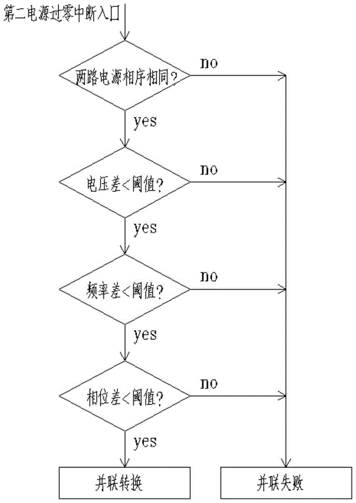
[0005] At present, the existing automatic power conversion system with parallel conversion function can realize uninterrupted switching of power sources. It judges the phase sequence, voltage difference, frequency difference, and phase difference of the two power sources, and only when the conditions are met can the first switch be used. When the set threshold is large, the closing current of the parallel connection will be large, which will affect the normal operation of the two power supplies. When the set threshold is small, it is easy to cause two circuits Parallel connection of power supply failed

Method used


Image

  • A control method of a parallel power conversion device and a parallel power conversion device
  • A control method of a parallel power conversion device and a parallel power conversion device
  • A control method of a parallel power conversion device and a parallel power conversion device

Examples


Embodiment Construction

[0041] The technical scheme of the present invention is described in detail below in conjunction with accompanying drawing:

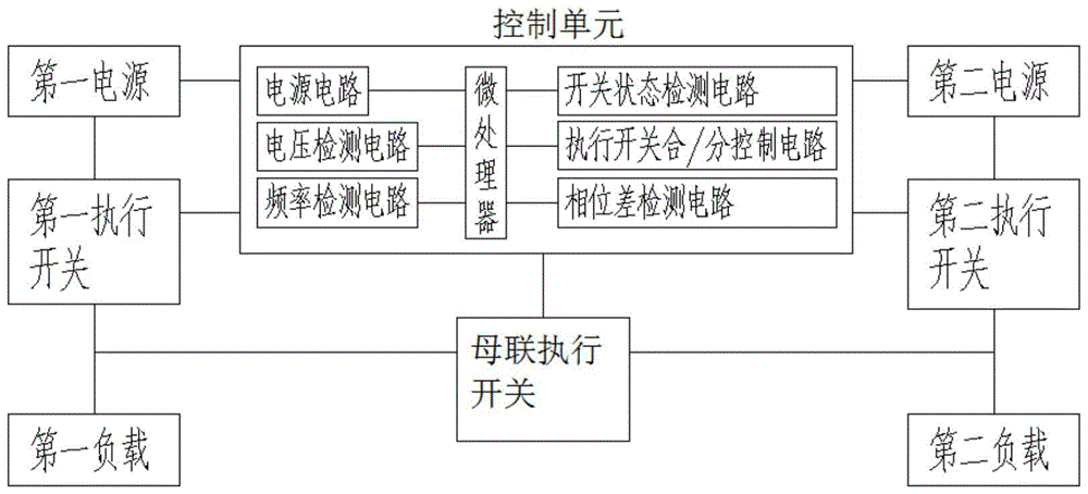
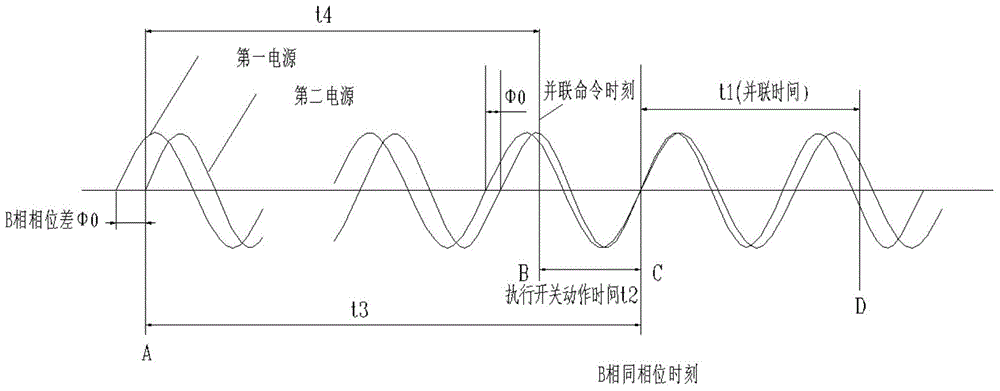
[0042] The present invention provides a parallel conversion control method for the existing automatic power conversion system with a parallel conversion function, which has a relatively large closing current. The idea is to receive an external parallel conversion command and determine the After the phase sequence, voltage difference, and frequency difference meet the preset requirements, the parallel conversion is not performed immediately, but the best parallel conversion period that can minimize the loop closing current is selected according to the phase difference of the two power sources, that is, the parallel state is guaranteed The initial moment is located at the same phase as the input of the first power supply input terminal and the second power supply input terminal, and parallel conversion is performed during this period, thereby effectively r...


PUM


Abstract

The invention discloses a control method of a parallel-connection power source conversion device, and belongs to the technical field of low-voltage electric appliances. In order to overcome the defect that an existing automatic power source conversion system with a parallel-connection conversion function has large loop current, the parallel-connection conversion control method is provided. According to the thought, after an external parallel-connection conversion instruction is received and it is determined that the phase sequence, voltage difference and frequency difference of two paths of power sources meet preset requirements, parallel-connection conversion is not executed immediately, instead, the best parallel-connection conversion period with the smallest loop current is selected according to the phase difference of the two paths of power sources, and parallel-connection conversion is carried out during the period. The invention further discloses the parallel-connection power source conversion device and a power source system. Compared with the prior art, the control method of the parallel-connection power source conversion device and the parallel-connection power source conversion device can effectively lower the loop current in the parallel connection process of two paths of power sources, improve safety, are easy to realize, and are wider in application range.

Description

technical field [0001] The invention relates to a control method of a parallel power conversion device and a parallel power conversion device, which belong to the technical field of low-voltage electrical appliances. Background technique [0002] Automatic power transfer switches have been widely used in industrial power supply systems, but in the case of two power supplies and two loads, if the two power supplies supply power to the two loads separately under normal power supply conditions, if any one fails, most existing The automatic power transfer switch cannot make the other power supply that has not failed to supply power to the two loads at the same time, so that the load cannot be powered and work. [0003] In order to solve the above problems, a bus tie executive switch can be connected between the input sides of the two loads, and it can be realized by using a system composed of PLC and relays to control the two power supply executive switches and the bus tie execu...

Claims


Application Information

Patent Timeline
Patent Type & Authority Patents(China)
IPC IPC(8): H02J9/06
Inventor 顾怡文季春华钱宽
Owner CHANGSHU SWITCHGEAR MFG CO LTD (FORMER CHANGSHU SWITCHGEAR PLANT)
Learn More