Ash removal device for tail flue of fluidized boiler

A tail flue, fluidization technology, applied in axial flow pump, removal of solid residue, combustion product treatment, etc., can solve the problems of low ash removal efficiency and large flow resistance, so as to improve ash removal efficiency and Spray speed and degree of atomization, the effect of easy cleaning

Active Publication Date: 2018-01-12
BRIGHT THERMAL EQUIP CO LTD
View PDF8 Cites 0 Cited by
  • Summary
  • Abstract
  • Description
  • Claims
  • Application Information

AI Technical Summary

Problems solved by technology

[0009] The technical problem to be solved by the present invention is: to overcome the low ash removal efficiency and large flow resistance of traditional equipment in the prior art

Method used


Image

  • Ash removal device for tail flue of fluidized boiler

Examples


Embodiment Construction

[0034] The present invention is described in further detail now in conjunction with accompanying drawing. These drawings are all simplified schematic diagrams, which only illustrate the basic structure of the present invention in a schematic manner, so they only show the configurations related to the present invention.

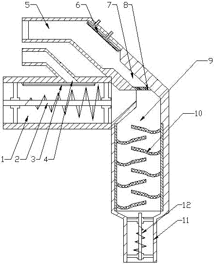
[0035] Such as figure 1 Shown, the present invention is a kind of ash removal device of fluidized boiler tail flue, comprises smoke inlet pipe 1, cooling pipe 5, separation pipe 9 and settling pipe; Wherein separation pipe 9 is a semi-closed cylindrical pipe, The axis of the cylindrical duct is perpendicular to the ground, the open end of the cylindrical duct faces the ground, and the smoke inlet pipe 1 is arranged on the side wall of the cylindrical duct;

[0036] The smoke inlet pipe 1 is open at both ends, one end of the smoke inlet pipe 1 communicates with the inside of the cylindrical pipe, and the other end of the smoke inlet pipe 1 communicates with th...


PUM


Abstract

The invention relates to an ash removing device of the tail flue of a fluidized boiler. The ash removing device comprises a smoke inlet pipe, a cooling pipe, a separation pipe and a sedimentation pipe, wherein the axis of the columnar pipeline of the separation pipe is vertical to the ground, the open end of the columnar pipeline faces to the ground, and the smoke inlet pipe is arranged on the lateral wall of the columnar pipeline; one end of the smoke inlet pipe is communicated with the interior of the columnar pipeline, and the other end thereof is communicated with the tail flue of the fluidized boiler; the cooling pipe is mounted at the sealed end at the top of the separation pipe, the other end of the cooling pipe is communicated with the interior of the separation pipe, and a spraying component is mounted in the cooling pipe; a separator is disposed on the wall face of the separation pipe and comprises a plurality of filter plates, and the filter plates are arranged on the inner wall of the separation pipe in a zigzag and staggered manner; an exhaust pipe is arranged at the bottom of the separation pipe. The ash removing device has the advantages that smoke is absorbed through water, and separation of waste gas, particles and soluble impurities is achieved by the filtering separation mechanism.

Description

technical field [0001] The invention relates to an ash removal device for a tail flue of a fluidized boiler, which belongs to the exhaust gas purification equipment of a fluidized boiler [0002] field. Background technique [0003] In the fluidized boiler, although the tail flue gas passes through the cyclone separator, most of the dust and powder can be separated. [0004] Coal ash, but there will still be a large part of the smoke and dust will be discharged into the atmosphere along with the tail smoke, causing environmental pollution, and at the same time [0005] At the same time, there is also a lack of corresponding purification equipment for gases such as sulfur dioxide and sulfur trioxide, and they will also be discharged into the atmosphere along with the tail flue gas. [0006] In the middle, it will cause serious pollution to the environment; at the same time, the smoke and acidic air will also corrode the inner wall of the chimney, and the inner wall of the c...

Claims


Application Information

Patent Timeline
Patent Type & Authority Patents(China)
IPC IPC(8): F23J3/02F23J15/00
CPCF04D19/00F23J15/006F23J15/022F23J15/025F23J15/06F23J2217/10F23J2217/50
Inventor 吴杨平董凯邓大双
Owner BRIGHT THERMAL EQUIP CO LTD
Why Eureka
Try Eureka