Non-power-energy-consumption water intake facility

A technology with no power consumption, applied in water supply devices, drinking water devices, buildings, etc., can solve problems such as unstable blood pressure, danger, and difficulty in fetching water

Inactive Publication Date: 2015-05-27
陈科
View PDF6 Cites 4 Cited by
  • Summary
  • Abstract
  • Description
  • Claims
  • Application Information

AI Technical Summary

Problems solved by technology

Some rural families set up water pumps in the wells, but many housewives or elderly people often do not use the water pumps in order to save electricity, but use a bucket to draw water into the well. It is not easy to pull the full water bucket from the well, especially for the elderly, it is not only tiring but also dangerous, because many elderly people suffer from high blood pressure. Cardiovascular diseases such as blood pressure, these elderly people often bend over and lower their heads to...

Method used


Image

  • Non-power-energy-consumption water intake facility
  • Non-power-energy-consumption water intake facility
  • Non-power-energy-consumption water intake facility

Examples


Embodiment Construction

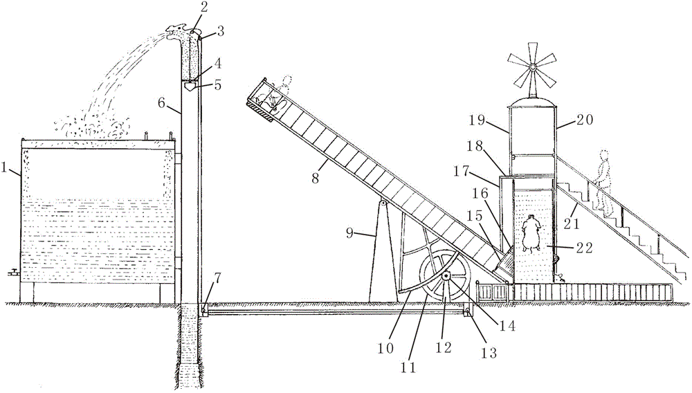
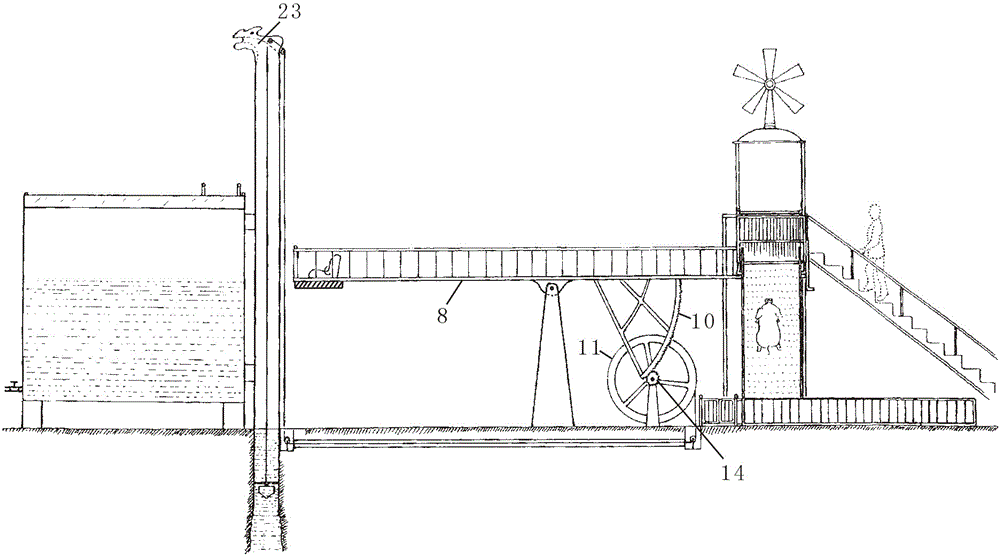
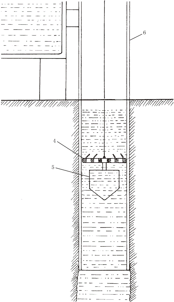
[0022] Embodiments of the present invention will be further described in conjunction with the accompanying drawings.

[0023] Such as Figure 1-8 As shown in the figure, 1. water storage tank, 2. A pulley, 3. B pulley, 4. clapboard, 5. vertical head, 6. bobbin tube, 7. C pulley, 8. seesaw, 9. seat frame, 10. Rack, 11. Rope reel, 12. Support seat, 13. D pulley, 14. Pinion, 15. Lower platform, 16. Upper platform, 17. Widening column, 18. Beam, 19. Front left Column, 20. Front right column, 21. Ladder, 22. Inclined bridge, 23. Outlet channel, 24. Elevated platform, 25. Pedal, 26. First bolt frame, 27. Second bolt frame, 28. Safety Rod, 29. Shaft, 30. Slider, 31. Frame, 32. Step, 33. Strut, 34. Button hole, 35. Ramp, 36. Positioning device, 37. Spring, 38. Ninth Pulley, 39. The third wire rope, 40. The first pulley, 41. The second pulley, 42. The third pulley, 43. The first wire rope, 44. Foot switch, 45. Cushion, 46. Cushion, 47. Fixed flat plate, 48. The fourth pulley, 49. Li...


PUM

PropertyMeasurementUnit
Heightaaaaaaaaaa

Abstract

The invention discloses a non-power-energy-consumption water intake facility. The non-power-energy-consumption water intake facility is characterized in that a water well equipped with a tube is arranged beside a water reservoir; a water outlet channel on the top of the tube is positioned above the water reservoir; a water intake device with a steel rope is arranged in the tube; the steel rope penetrates through the tube and is connected with a rope winding coil on a rotating shaft through a pulley and the like; the rotating shaft equipped with a pinion is connected with a supporting seat; the pinion is connected with a rack on the bottom surface of the rear part of a warped plate; the middle of the warped plate and a seat frame are connected in a moving way; an upper-layer platform and a lower-layer platform with railings are arranged at the tail of the warped plate; openings are formed in the right side and the front side of the lower-layer platform; a pedal is arranged in the opening in the front side; an elevated platform is arranged in front of the pedal and is connected with the rear part of a skew bridge; an inlet/out is formed in the rear side of the upper-layer platform; an elevated pavilion is arranged behind the inlet/out; inlet/outs are formed in the front side and the right side of the elevated pavilion; a ladder is arranged at the inlet/out in the right side of the pavilion; a ramp entrance is formed below the warped plate at the right side of the rope winding coil; a ramp and the front end of the landed skew bridge are connected; steps corresponding to the inlet/out in the upper-layer platform are arranged outside the ramp; a ground trough is formed in the ramp; a lifting plate corresponding to the opening in the right side of the lower-layer platform is arranged in the ground trough.

Description

technical field [0001] The invention relates to a water intake facility, in particular to a non-electric energy consumption water intake facility. Background technique [0002] Many rural households have wells. Rural households without tap water use well water, but many rural households with tap water often use well water instead of tap water in order to save costs. Some rural families set up water pumps in the wells, but many housewives or elderly people often do not use the water pumps in order to save electricity, but use a bucket to draw water into the well. It is not easy to pull the full water bucket from the well, especially for the elderly, it is not only tiring but also dangerous, because many elderly people suffer from high blood pressure. Cardiovascular diseases such as blood pressure, these elderly people often bend over and lower their heads to fetch water into the well, which is prone to unstable blood pressure and lead to cerebral hemorrhage, myocardial infar...

Claims


Application Information

Patent Timeline
IPC IPC(8): E03B3/10E03B3/40E04H14/00
Inventor 陈科
Owner 陈科
Why Eureka
Try Eureka