Simple rotary cutting mechanism

A simple, rotary cutting groove technology, applied in the manufacture of veneer, wood processing equipment, manufacturing tools, etc., can solve the problems of complex structure of rotary cutting machine, complicated rotary cutting operation, etc.

Inactive Publication Date: 2015-07-08
周玉翔
View PDF7 Cites 3 Cited by
  • Summary
  • Abstract
  • Description
  • Claims
  • Application Information

AI Technical Summary

Problems solved by technology

The structure of the rotary cutting machine is complicated, and the rotary cutting operation is complicated

Method used


Image

  • Simple rotary cutting mechanism
  • Simple rotary cutting mechanism
  • Simple rotary cutting mechanism

Examples


Embodiment Construction

[0013] The preferred embodiments of the present invention will be described in detail below in conjunction with the accompanying drawings, so that the advantages and features of the present invention can be more easily understood by those skilled in the art, so as to define the protection scope of the present invention more clearly.

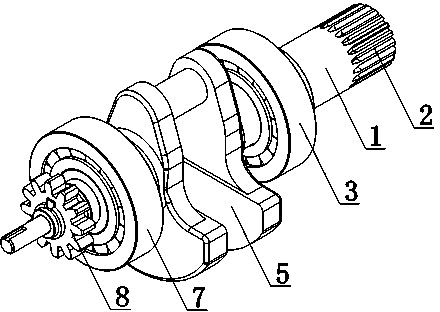
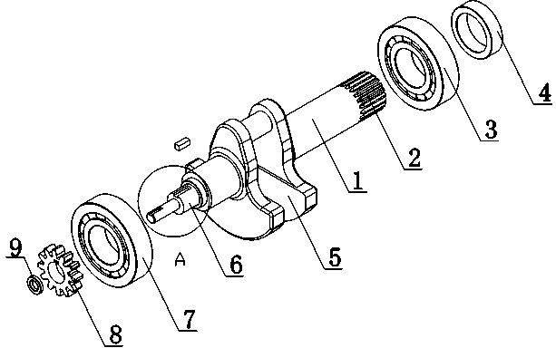
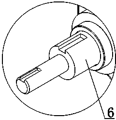
[0014] Such as Figure 1 to Figure 3 As shown, a simple rotary cutting mechanism includes a driving tube 1, one end of the driving tube 1 is provided with a rotary cutting groove 2, the driving tube 1 is provided with a swing block 5, and the driving tube 1 is equipped with a first plane bearing 3, the first The plane bearing 3 is in contact with the oscillating block 5, and the connection position between the plane bearing 3 and the driving tube 1 is provided with a collar 4, and the oscillating block 5 is provided with a driving end 6, and the driving end 6 is fitted with the second plane bearing 7 and the driving gear 8, and the oscillating Th...


PUM


Abstract

The invention discloses a simple rotary cutting mechanism. The mechanism comprises a driving pipe; a rotary cutting groove is formed in one end of the driving pipe; the driving pipe is provided with an oscillating block and sleeved with a first plane bearing, wherein the first plane bearing is in contact with the oscillating block; a sleeve ring is arranged at the part in which the plane bearing is connected with the driving pipe; the oscillating block is provided with a driving end which is sleeved with a second plane bearing and a driving gear. According to the mechanism, the driving end is externally connected with a driving motor; the driving motor can directly control the driving gear to rotate so as to achieve the rotating control of the driving pipe; the rotary cutting groove in the end part of the driving pipe can achieve the rotary cutting function, so that an article can be conveniently treated by rotary cutting.

Description

technical field [0001] The invention relates to a rotary cutting mechanism, in particular to a simple rotary cutting mechanism. Background technique [0002] Rotary cutting machine is one of the main equipment for producing plywood. It is divided into card rotary cutting machine and non-card rotary cutting machine. With the advancement of technology, digital servo control technology is also applied to the production of rotary cutting machine. In recent years Appeared CNC rotary cutting machine. The emergence of CNC rotary cutting machine not only improves the quality and precision of veneer production, but also greatly improves the production efficiency and the degree of automation of the whole machine. The rotary cutting machine has complex structure and complex rotary cutting operation. Contents of the invention [0003] The present invention mainly solves the technical problems existing in the prior art, thereby providing a drive end that can be externally connected ...

Claims


Application Information

Patent Timeline
Patent Type & Authority Applications(China)
IPC IPC(8): B27L5/02
CPCB27L5/02
Inventor 周玉翔
Owner 周玉翔
Why Eureka
Try Eureka