Current converter module unit, current converter, DC power transmission system and control method

A modular unit and inverter technology, applied in the direction of converting AC power input to DC power output, electrical components, power transmission AC network, etc., can solve the problem of poor consistency of high-potential energy acquisition and monitoring of inverters, and clear faults Long dynamic response time, inconsistent rising rate of capacitor voltage, etc., to achieve the effect of quickly clearing DC short-circuit faults, good DC fault ride-through capability, and less components

Active Publication Date: 2015-08-26
NR ELECTRIC CO LTD
View PDF3 Cites 12 Cited by
  • Summary
  • Abstract
  • Description
  • Claims
  • Application Information

AI Technical Summary

Problems solved by technology

[0006] The clamp dual module is composed of two traditional half-bridge modules cascaded through a full-control switch and two clamp diodes. Compared with the full-bridge module, the number of full-control switches is effectively reduced and the operating loss is reduced. Problems: First, when the clamping dual module is in the state of all full-control switches locked, due to the asymmetric structure of the diode in the topology, the equivalent capacitance of each bridge arm is inconsistent when starting AC charging, and the capacitor voltage The rise rate is inconsistent, which makes the consistency of the high-potential energy acquisition and monitoring of the entire converter poor, which is likely to cause system misjudgment; second, when the DC fault occurs, the two DC support capacitors of the clamping dual module are connected in parallel to the AC Between the system voltage and the fault point, the DC voltage of the module rises slowly, and the dynamic response time for clearing the fault is longer

Method used


Image

  • Current converter module unit, current converter, DC power transmission system and control method
  • Current converter module unit, current converter, DC power transmission system and control method
  • Current converter module unit, current converter, DC power transmission system and control method

Examples


Embodiment Construction

[0057] The technical solutions of the present invention will be described in detail below in conjunction with the accompanying drawings.

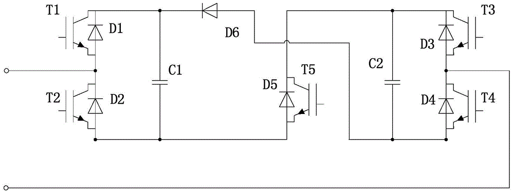
[0058] Such as figure 1 As shown, the present invention provides a converter module unit, including two energy storage elements C1, C2, 5 switch modules and a diode D6, wherein the negative pole of the first switch module is connected to the positive pole of the second switch module, and the second switch module is connected to the positive pole of the second switch module. The anode of a switch module is connected to the anode of the first energy storage element, the cathode of the second switch module is connected to the cathode of the first energy storage element C1; the cathode of the diode D6 is connected to the anode of the first switch module, and the anode of the diode D6 is respectively connected to the second The negative pole of the energy storage element C2 and the negative pole of the fourth switch module, and the positive pole...


PUM


Abstract

A current converter module unit, a converter, a direct-current transmission system and a control method. In the converter module unit, the positive electrode of a first switch module (T1, D1) is connected to the positive electrode of a first energy storage element (C1), and the negative electrode of a second switch module (T2, D2) is connected to the negative electrode of the first energy storage element; the negative electrode of a diode (D6) is connected to the positive electrode of the first switch module, the positive electrode of the diode is respectively connected to the negative electrode of a second energy storage element (C2) and the negative electrode of a fourth switch module (T4, D4), the positive electrode of the fourth switch module is connected to the negative electrode of a third switch module (T3, D3), and the positive electrode of the second energy storage element is connected to the positive electrode of the third switch module; and the positive electrode of the third switch module is connected to the positive electrode of a fifth switch module (T5, D5), and the negative electrode of the fifth switch module is connected to the negative electrode of the second switch module. This structure can provide a favourable direct-current side fault ride-through performance, thereby overcoming the limitation and deficiency of structures such as a full-bridge module and a clamping double-module, and having better economical and technological performances.

Description

technical field [0001] The invention belongs to the field of flexible DC power transmission, and in particular relates to a converter module unit, a modular multilevel converter based on the converter module unit, a DC power transmission system, and the aforementioned converter module unit, modular multilevel converter A level converter and a control method for a direct current transmission system. Background technique [0002] The core of the flexible DC transmission system is the voltage source converter based on fully controlled devices. Multi-level technology is the optimal solution for realizing high-voltage and large-capacity voltage source converters. Compared with the two-level converter, the multi-level converter can use low-voltage devices to achieve high-voltage level output without direct series connection of switching devices. In recent years, the emergence of Modular Multilevel Converter (MMC) has enabled the successful application of MMC in the field of flex...

Claims


Application Information

Patent Timeline
Patent Type & Authority Applications(China)
IPC IPC(8): H02M7/00H02M7/66H02M1/32H02J3/36
CPCH02M7/483H02M7/4835
Inventor 谢晔源曹冬明邵震霞董云龙
Owner NR ELECTRIC CO LTD
Why Eureka
Try Eureka