Modular multilevel converter and converter module

A technology of converters and sub-modules, applied in the field of converters, can solve the problems of large loss and long dynamic response time, and achieve the effects of fast dynamic response, good comprehensive performance, and good DC fault ride-through capability

Inactive Publication Date: 2016-01-13
NR ELECTRIC CO LTD +1
View PDF3 Cites 2 Cited by
  • Summary
  • Abstract
  • Description
  • Claims
  • Application Information

AI Technical Summary

Problems solved by technology

[0006] The purpose of the present invention is to overcome the deficiencies in the prior art, provide a converter module, and solve the technical problems in the prior art that the dynamic response time is long and the loss is large when quickly clearing the DC short-circuit fault

Method used


Image

  • Modular multilevel converter and converter module
  • Modular multilevel converter and converter module
  • Modular multilevel converter and converter module

Examples


Embodiment 1

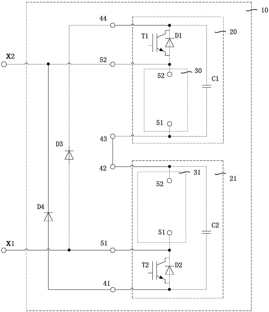
[0065] Such as figure 1 As shown, the converter module includes a first terminal X1, a second terminal X2, a diode D3, a diode D4, a first half-bridge 20 and a second half-bridge 21, and the first half-bridge 20 includes a first switch unit 30. The first switch module and the energy storage element C1, the first switch module and the energy storage element C1 are connected in parallel at both ends of the first switch unit 20; the second half bridge 21 includes a second switch unit 31, a second switch module and the energy storage element C2, the second switch module is connected in parallel with the energy storage element C2 at both ends of the second switch unit 31; the negative pole of the energy storage element C1 is connected to the positive pole of the energy storage element C2;

[0066] The anode of the diode D3 is connected to the first terminal X1, and the cathode is connected to the node of the first switch module and the energy storage element C1;

[0067] The cath...

Embodiment 2

[0078] The difference from Embodiment 1 is that the first switch unit 30 and the second switch unit 31, such as Figure 6 As shown, the first switch unit 30 and the second switch unit 31 include two switch unit sub-modules connected in reverse series.

[0079] The switch unit sub-module includes a switch tube T53 and an antiparallel diode D53, or a switch tube T54 and an antiparallel diode D54. and remember as Figure 6 As shown, the module formed by connecting the collectors of the switch tubes in the two switch unit sub-modules is a switch unit 33, that is, the first switch unit 30 adopts the circuit of the switch unit 33, and the second switch unit 31 also adopts the switch unit 33 circuit.

Embodiment 3

[0081] The difference from Embodiment 1 is that the second switch unit 31, such as Figure 7 As shown, the second switch unit (21) includes a switch unit submodule, and the switch unit submodule includes a switch tube T55 and an antiparallel diode D55, and is recorded as Figure 7 As shown, one switch unit sub-module is the switch unit 34 , that is, the first switch unit 30 adopts the circuit of the switch unit 32 , and the second switch unit 31 adopts the circuit of the switch unit 34 .


PUM


Abstract

The invention discloses a converter module, which comprises a first leading-out end X1, a second leading-out end X2, a first half-bridge and a second half-bridge, wherein each of the first half-bridge and the second half-bridge comprises a switching unit, a switching module and an energy storage element, and each switching module is serially connected with the corresponding energy storage element and then connected on both ends of the corresponding switching unit in parallel. The converter module can achieve the function of eliminating DC short circuit failure, and has good comprehensive performance of operating loss and faulty current suppression effect. The invention further discloses a modular multilevel converter, which comprises at least one phase unit, wherein each phase unit consists of a plurality of serially-connected converter modules. The modular multilevel converter can achieve the functions of conversion between alternating current and direct current, multilevel voltage sources and DC short circuit failure elimination, and can be applied to reactive power compensation equipment, active or reactive generation equipment, applications for electric energy feedback and the like.

Description

technical field [0001] The invention relates to a converter module, and also relates to a modular multilevel converter, which belongs to the technical field of converters. Background technique [0002] The core of the flexible DC transmission system is the voltage source converter based on fully controlled devices. Multi-level technology is the optimal solution for realizing high-voltage and large-capacity voltage source converters. Compared with the two-level converter, the multi-level converter can use low-voltage devices to achieve high-voltage level output without direct series connection of switching devices. In recent years, the emergence of Modular Multilevel Converter (MMC) has enabled the successful application of multilevel converters in the field of flexible DC transmission. The converter of the modular multilevel converter adopts a modular design, which is composed of several basic unit modules with the same structure connected in series. Each module is called ...

Claims


Application Information

Patent Timeline
IPC IPC(8): H02M7/00H02M1/32
Inventor 谢晔源曹冬明田杰姜田贵朱铭炼
Owner NR ELECTRIC CO LTD
Why Eureka
Try Eureka