Segmented grinding method for large rotor of screw compressor

A screw compressor and rotor technology, applied in the field of machining, can solve the problems of increasing the size of the machine tool, increasing the load of the motor, affecting the machining accuracy, etc., and achieving the effects of high machining accuracy, convenient modification and modification, and low production cost

Inactive Publication Date: 2015-09-23
SHAANXI UNIV OF TECH +1
View PDF6 Cites 8 Cited by
  • Summary
  • Abstract
  • Description
  • Claims
  • Application Information

AI Technical Summary

Problems solved by technology

However, there are many problems to be solved in the process of forming grinding wheel grinding. With the development of machinery manufacturing industry, screw compressors, which are widely used in mining, construction, aviation and other fields, are becoming larger and larger. The screw rotor also becomes larger, which puts forward higher requirements for the processing of the screw rotor. The large tooth groove width of the helical surface makes the grinding wheel form grinding face a huge challenge. The matching shaped grinding wheel will increase the thickness of the grinding wheel, so the following problems arise: As the thickness of the grinding wheel increases, the quality of the grinding wheel will inevitably increase, the grinding area will increase, and the grinding force will increase; the quality of the grinding wheel will increase. Increasing the rigidity of the machine tool bed puts forward higher requirements, increasing the size of the machine tool and increasing the load of the motor; the rotation of the large grinding wheel will cause relatively strong vibration of the machine tool, which will affect the machining accuracy, and will inevitably put forward higher requirements for machine tool manufacturing

Method used


Image

  • Segmented grinding method for large rotor of screw compressor
  • Segmented grinding method for large rotor of screw compressor
  • Segmented grinding method for large rotor of screw compressor

Examples


Embodiment Construction

[0069] The present invention will be described in detail below with reference to the drawings and specific embodiments.

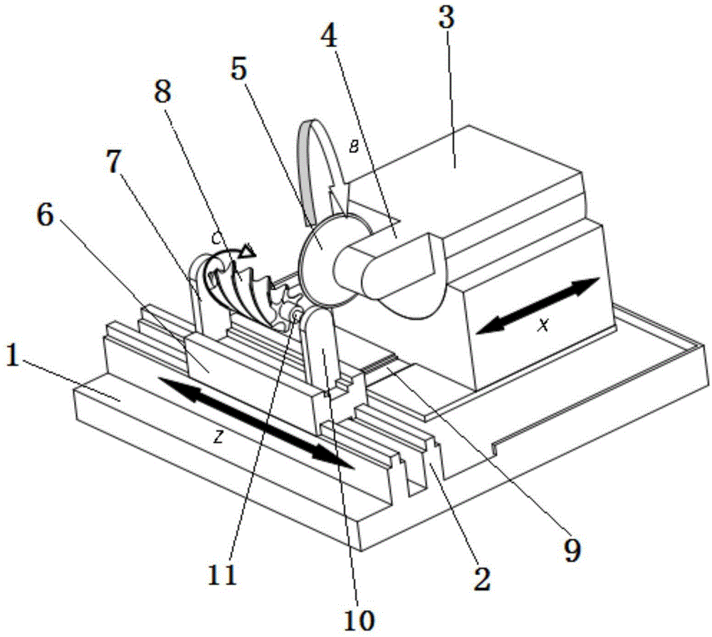
[0070] The segmented grinding device used in the present invention has a structure such as figure 1 As shown, the bed 1 is included. The bed 1 is provided with a transverse guide rail 2 and a longitudinal chute 9 respectively. The transverse guide rail 2 and the longitudinal chute 9 are perpendicular to each other; the longitudinal chute 9 is provided with a grinding wheel stand 3, which can Move along the longitudinal chute 9; one side of the grinding wheel frame 3 is provided with a boss 4, and one side of the boss 4 is provided with a grinding wheel 5; the horizontal guide 2 is provided with a worktable 6, which can move along the guide 2 The workbench 6 is provided with a headstock 7 and a tailstock 10 parallel to each other, the headstock 7 is provided with a rotor clamping head for clamping the rotor workpiece 8, and the tailstock 10 is provided with a c...


PUM


Abstract

The invention discloses a segmented grinding method for a large rotor of a screw compressor. The method comprises the specific steps that 1, an arc grinding wheel is trimmed; 2, the rotor type linear value point is selected according to the initial segmented line spacing; 3, an envelope path of the arc grinding wheel to machine the rotor is computed; and 4, a spiral groove is machined in a segmented mode. The large screw rotor is ground in a segmented mode through the arc grinding wheel; under the condition of lowering the requirements for machining equipment, the spiral face of the large rotor is segmented, the relative position of the grinding wheel and a workpiece is adjusted, and by conducting precision machining on the large screw rotor in a segmented grinding mode, abrasion to a tool is lowered on the premise of ensuring the machining precision. The requirements for equipment size and loads are low; the grinding tool can conduct profiling conveniently and is small in profiling quantity; the machining precision is high; the production cost is low.

Description

Technical field [0001] The invention belongs to the technical field of mechanical processing methods, and specifically relates to a segmented grinding method of a rotor of a large screw compressor. Background technique [0002] In recent years, screw compressors have been widely used in machinery, chemical industry, metallurgy, construction, mining, and aerospace due to their stable high-speed operation, multi-phase mixed transmission, almost no impact on exhaust pressure and easy operation and maintenance. In the industrial field, the processing problem of screw rotor as its core component has received extensive attention. [0003] With the increasing maturity of forming grinding technology, forming grinding is increasingly used in the finishing of complex curved surfaces. The finishing of screw rotors for air compressors often uses forming grinding wheel grinding. However, there are many problems that need to be solved in the process of forming grinding wheel grinding. With the ...

Claims


Application Information

Patent Timeline
Patent Type & Authority Applications(China)
IPC IPC(8): B24B1/00
CPCB24B1/00
Inventor 姚斌向明新张东生贾智杰沈志煌唐峰博冯文平管大渊
Owner SHAANXI UNIV OF TECH
Why Eureka
Try Eureka