

Microfluidic chip droplet generation device
A microfluidic chip and droplet generation technology, applied in laboratory utensils, laboratory containers, chemical instruments and methods, etc., can solve the problems of complex control process and many control droplet generation devices, and achieve the generation conditions. Simple, small device size, easy to carry
- Summary
- Abstract
- Description
- Claims
- Application Information
AI Technical Summary
Problems solved by technology
Method used
Image

Examples
Embodiment 1
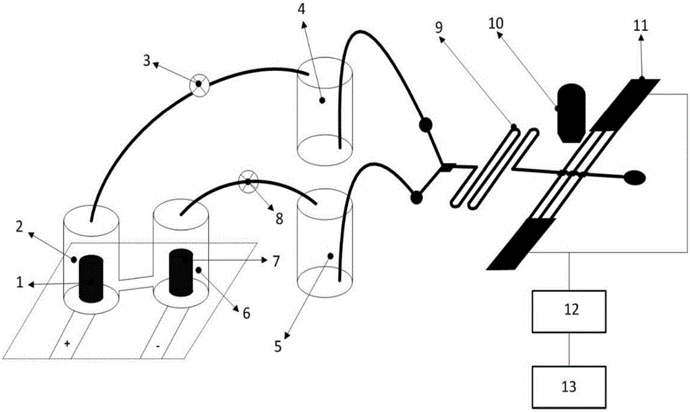
[0022] Embodiment 1 (see figure 1 )
[0023] All the effusion bottles are cylindrical bottles with an inner diameter of 16mm, an outer diameter of 20mm, and a height of 30mm. They are placed independently, and the applied DC voltage is 0-30V. The first electrode 1 and the second electrode 7 are both graphite electrodes. The first electrode 1 is connected to the positive pole of the DC power supply, and the second electrode 7 is connected to the negative pole of the DC power supply. When the DC power supply is powered on, the saturated salt water in the first reaction liquid accumulation bottle 2 is electrolyzed to generate chlorine gas, which enters the oil storage liquid accumulation bottle 4 through the first pressure valve 3, and the dimethyl in the oil storage liquid accumulation bottle 4 The silicone oil is pressed into the oil channel of the microfluidic chip 9, and at the same time, the saturated salt water in the second reaction liquid accumulation bottle 6 is electro...
Embodiment 2
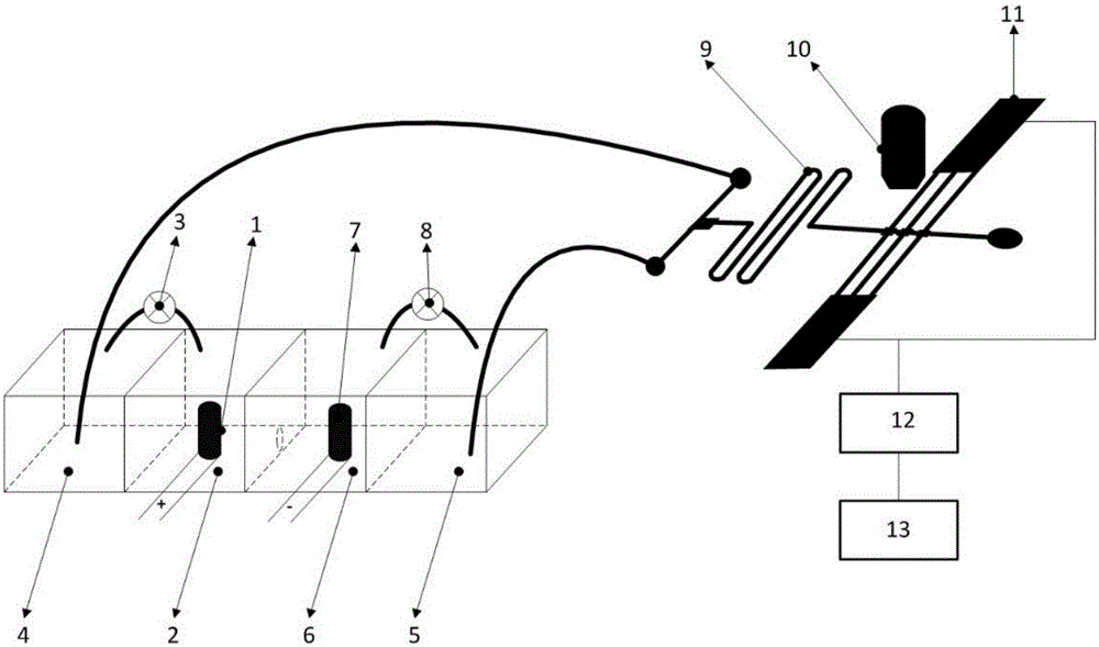
[0024] Embodiment 2 (see figure 2 )
[0025]All effusion bottles are cuboids with a bottom surface of 25mm×25mm and a height of 20mm. All effusion bottles are placed side by side to form a 1×4 pattern, resulting in a cuboid structure with a size of 100mm×25mm×20mm; the applied DC voltage is 0-30V , the first electrode 1 and the second electrode 7 are pencil leads, the first electrode 1 is connected to the positive pole of the DC power supply, and the second electrode 7 is connected to the negative pole of the DC power supply. Distilled water is housed in the water storage liquid accumulation bottle 5, and simethicone oil is housed in the oil storage liquid accumulation bottle 4. When the DC power supply is powered on, the saturated salt water in the first reaction liquid accumulation bottle 2 is electrolyzed to generate chlorine gas, which enters the oil storage liquid accumulation bottle 4 through the first pressure valve 3, and the simethicone in the oil storage liquid acc...
Embodiment 3
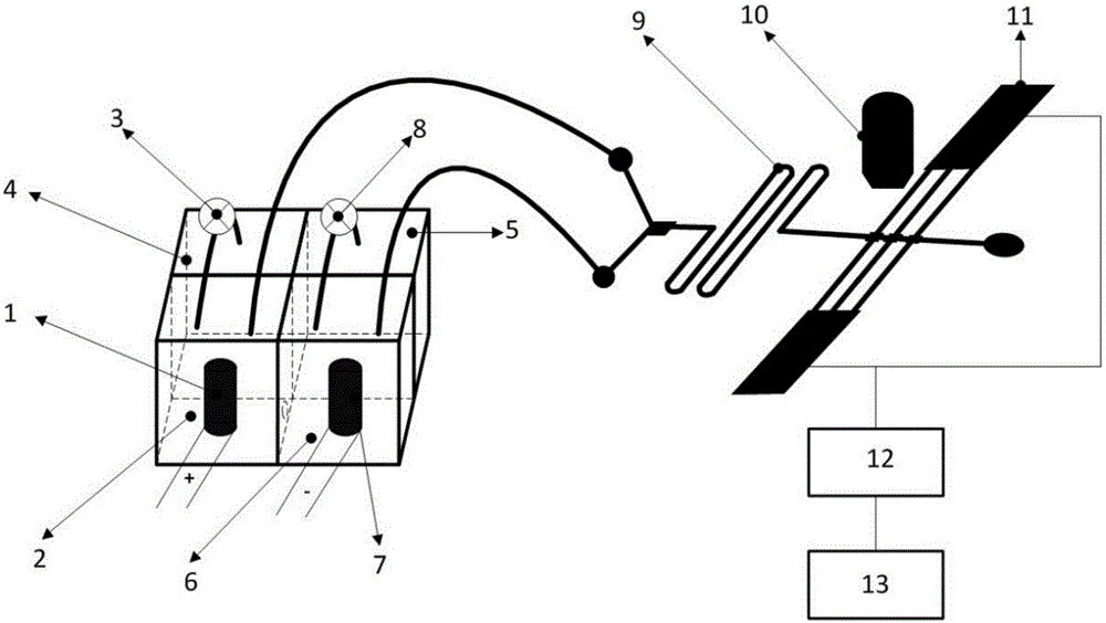
[0026] Embodiment 3 (see image 3 )
[0027] All the effusion bottles are cuboids with a bottom surface of 20mm×20mm and a height of 15mm. All the effusion bottles form a 2×2 pattern to obtain a cuboid structure with a size of 40mm×40mm×15mm; the applied DC voltage is 0-30V, the first Both the electrode 1 and the second electrode 7 are three-dimensional electrodes, the first electrode 1 is connected to the positive pole of the DC power supply, and the second electrode 7 is connected to the negative pole of the DC power supply. The three-dimensional electrode consists of an anode-graphite plate, a cathode-stainless steel plate, and powdered activated carbon as filling electrodes; distilled water is contained in the water storage liquid storage bottle 5, and dimethyl silicone oil is housed in the oil storage liquid storage bottle 4. When the DC power supply is powered on, the saturated salt water in the first reaction liquid accumulation bottle 2 is electrolyzed to generate chl...
PUM
 Abstract
Description
Claims
Application Information