Clamping device and clamping method for thin-walled frame parts

A clamping device and parts technology, which is applied in the field of processing clamping devices for thin-walled frame parts, can solve the problems of difficult control of clamping force, machining accuracy error, and high cost, and achieve flexible operation, guaranteed stability, and dimensional applicability strong effect

Active Publication Date: 2017-12-05
UNIV OF SHANGHAI FOR SCI & TECH
View PDF6 Cites 0 Cited by
  • Summary
  • Abstract
  • Description
  • Claims
  • Application Information

AI Technical Summary

Problems solved by technology

The disadvantages of this clamping method are: 1) the oil is easy to cause pollution to the system equipment, the cost is high, and it is not environmentally friendly; processing; 3) In addition, because the shape of the mounting plate with grooves is relatively simple, it cannot meet the clamping of thin-walled frame parts with irregular shapes
The disadvantages of this clamping method are: 1) firstly, the vacuum generated by the atmosphere is used to clamp the parts, which requires very high surface quality of the blank parts; 2) and this clamping method cannot realize the positioning of the fixture once And clamping, it is necessary to add other accessories, and it takes a long time to adjust the fixture
3) The clamping force is difficult to control, and the shape of thin-walled parts is relatively limited
Although this clamping method is simple, its obvious disadvantage is that the traditional clamp can easily cause deformation of thin-walled frame parts due to its inability to control its clamping force, resulting in large errors in machining accuracy.
[0008] 1) The degree of flexibility is not high, the shape of the processed parts is relatively limited, and the rough and fine machining methods are limited
[0009] 2) The fixture adjustment time is long, the cost is high, and the clamping force is difficult to adjust and control
[0010] 3) The adaptability is poor, the adjustment of the fixture is too dependent on experience, and the accuracy is difficult to control

Method used


Image

  • Clamping device and clamping method for thin-walled frame parts
  • Clamping device and clamping method for thin-walled frame parts
  • Clamping device and clamping method for thin-walled frame parts

Examples


Embodiment 1

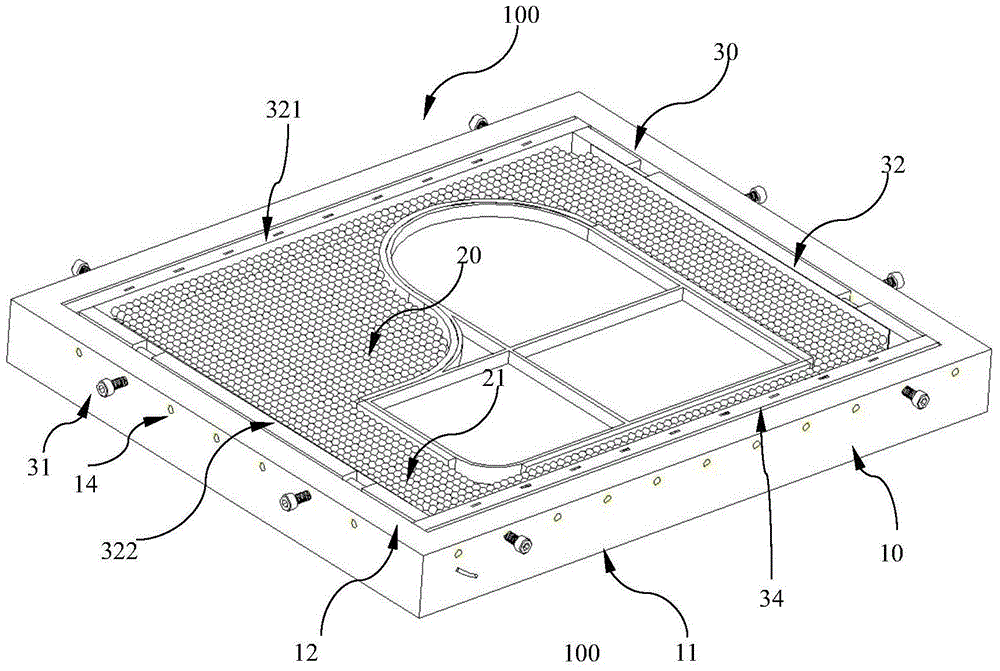
[0039] figure 1 It is a structural schematic diagram of the clamping device for the thin-walled frame parts of this embodiment

[0040] figure 2 It is a schematic diagram of the bottom plate of the clamping device and the internal electromagnet of the thin-walled frame parts of this embodiment

[0041] Such as figure 1 , as shown in 2, the clamping device 100 for thin-walled frame parts includes: a bottom plate portion 10 and a position limiting portion 20 disposed in the bottom plate portion and a clamping portion 30 for clamping the position limiting portion 20 .

[0042] in:

[0043] Bottom plate portion 10 is the groove shape of top opening, is rectangular, is used for accommodating parts to be processed, comprises bottom 11 and side 12, and its bottom 11 is hollow, and electromagnet 13 is arranged in it, is used for generating magnetic force after electrification, will The electromagnet is installed in the hollow part of the bottom plate part 10 to insulate and ensur...

Embodiment 2

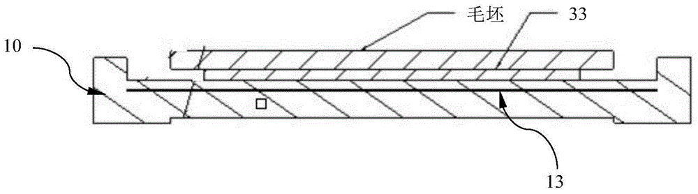
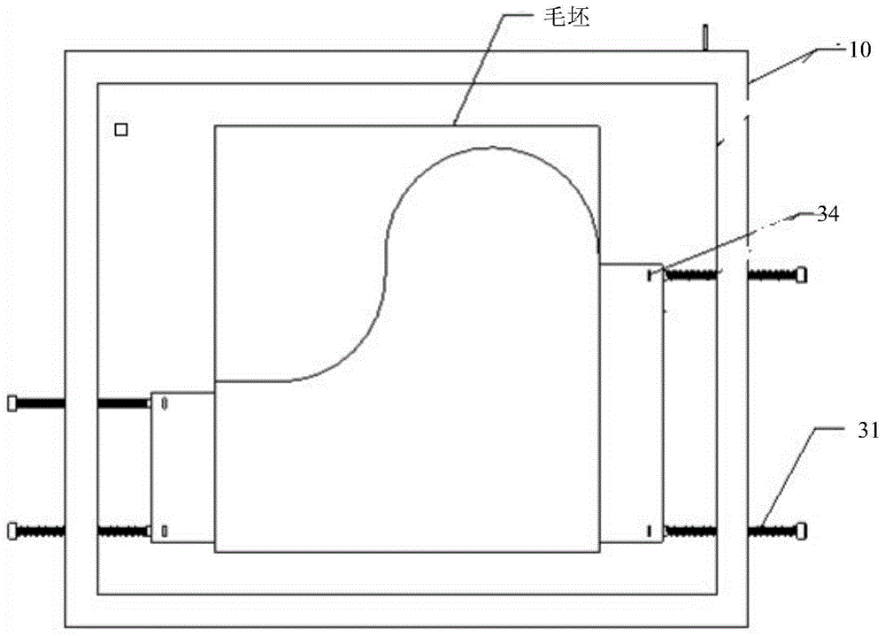
[0064] image 3 Schematic diagram of clamping for rough machining using the clamping device for thin-walled frame parts of the above embodiment

[0065] The process of clamping and processing on the processing machine using the clamping device for thin-walled frame parts in the above-mentioned embodiment 1 will be described in detail below.

[0066] Such as image 3 As shown, the blank of the rectangular thin plate part is clamped on the clamp body: the lower end surface of the blank is in contact with the upper end surface of the backing plate 33, the lower end surface of the backing plate 33 is in contact with the upper end surface of the bottom plate part 10 (with an electromagnet inside), and the blank passes through the stress. The measuring filler block 34 and the clamping rod 31 screw clamp the end faces on both sides to fix (that is, at this time, the two sets of sliding push plates 321 and the two sets of fixed push plates 322 have been disassembled), and the clampin...


PUM


Abstract

A clamping device for thin-walled frame type parts is used for clamping and fixing the non-magnetic thin-walled frame type parts to be machined when the parts are machined. The clamping device is characterized in that the device comprises a bottom plate portion and a position limiting portion; the bottom plate portion is in the shape of a groove with the upper part open and used for accommodating the parts to be machined; the bottom plate portion comprises a bottom and side edges, the bottom is hollow, and an electromagnet is arranged in the bottom and used for generating magnetic force after being powered on; the position limiting portion is arranged in the bottom plate portion and comprises a plurality of balls made of materials capable of being magnetized, and the balls are fixed at preset positions under the magnetic force effect and used for limiting the positions of the parts to be machined. Meanwhile, the invention provides a method used for clamping the parts through the clamping device for the thin-walled frame type parts.

Description

technical field [0001] The invention belongs to the field of mechanical devices, in particular to a processing and clamping device for thin-walled frame parts used in the fields of automobiles, aerospace and key precision processing. Background technique [0002] The processing of thin-walled parts in the field of mechanical processing is an unbreakable problem. With the increasing demand for small batches and many varieties of thin-walled parts in the current market, the cost of fixtures and processing will increase. In order to meet the needs of flexible thin-walled parts processing, especially to solve the problem of clamping design for thin-walled parts processing, this patent is mainly aimed at the processing of thin-walled frame parts. In the process of processing thin-walled frame parts, due to their special shape and low rigidity, the primary technical difficulty in processing is the clamping of thin-walled frame parts. The characteristics of thin-walled frame parts...

Claims


Application Information

Patent Timeline
Patent Type & Authority Patents(China)
IPC IPC(8): B23Q3/06
CPCB23Q3/065
Inventor 江小辉汪中厚赵超凡胡凯
Owner UNIV OF SHANGHAI FOR SCI & TECH
Why Eureka
Try Eureka