A magnetorheological flexible clamp for thin-walled parts with arbitrary shape

A technology of flexible fixtures and thin-walled parts, which is applied in the direction of clamping, manufacturing tools, metal processing machinery parts, etc., can solve the problems of affecting the processing accuracy of the workpiece, affecting the performance, and high cost, so as to achieve flexible operation, ensure stability, and suitable size strong effect

Active Publication Date: 2022-06-21
UNIV OF SHANGHAI FOR SCI & TECH +1
View PDF0 Cites 0 Cited by
  • Summary
  • Abstract
  • Description
  • Claims
  • Application Information

AI Technical Summary

Problems solved by technology

The disadvantages of this clamping method are: 1) Since the thin-walled parts are closely attached to the rubber, it is impossible to achieve effective control of the machining accuracy of the parts; 2) In addition, due to the deformation rate of the airbag, therefore Clamping of thin-walled parts that cannot meet irregular shapes
But its disadvantages are: 1) the top of the workpiece of this kind of fixture is not restrained, and vibration in the vertical direction may be generated during milling, thereby affecting the machining accuracy of the workpiece; 2) the space filled with magnetorheological fluid in this kind of fixture The cavity is not closed, it is easy to cause the magnetorheological fluid to overflow, and the chips are easily doped into the magnetorheological fluid, affecting its performance and reducing the service life of the magnetorheological fluid
[0008] 1. The existing fixture technology is greatly limited in terms of clamping accuracy and controllability;
[0009] 2. The fixture adjustment time is long, the cost is high, and the clamping force is difficult to adjust and control, the adaptability is poor, and the fixture adjustment is too dependent on experience;
[0010] 3. The degree of flexibility is not high, the shape of the processed parts is relatively limited, and the rough and fine machining methods are limited

Method used


Image

  • A magnetorheological flexible clamp for thin-walled parts with arbitrary shape
  • A magnetorheological flexible clamp for thin-walled parts with arbitrary shape
  • A magnetorheological flexible clamp for thin-walled parts with arbitrary shape

Examples


Embodiment

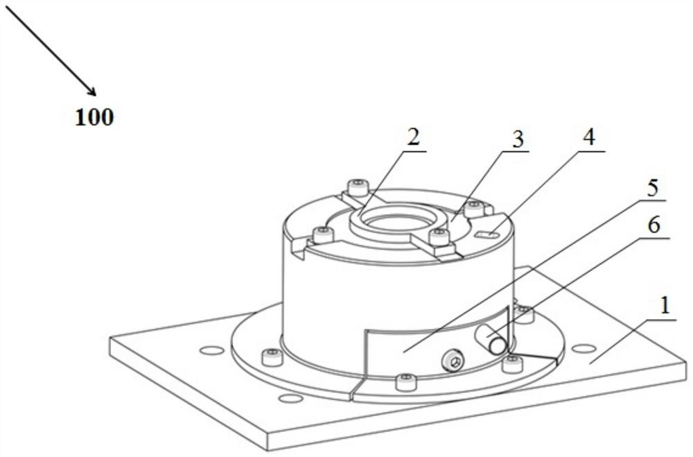
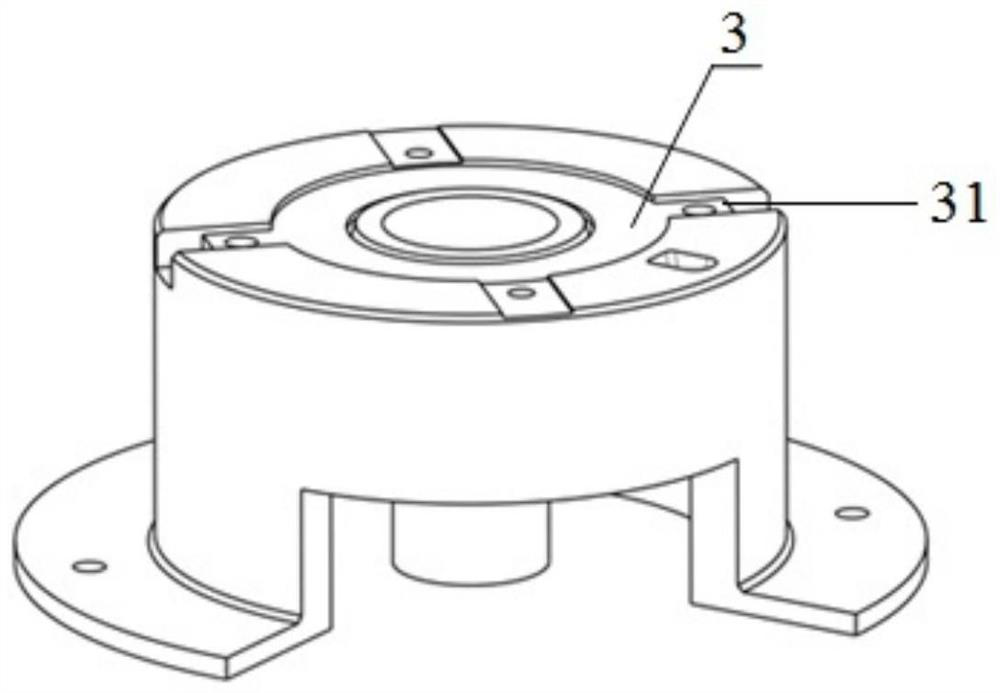
[0032] like figure 1 As shown, a magnetorheological flexible fixture 100 for thin-walled parts with arbitrary shapes in this embodiment is used for processing thin-walled parts 9 with arbitrary shapes, including: a base 1, a mechanical pressing part 2, a sealing cover 3, a liquid inlet Hole 4, mechanical clamping part 5 and drain pipe 6.

[0033] In this embodiment, the thin-walled parts 9 are thin-walled shells, frame-like parts, and the like.

[0034] The base 1 is placed on the workbench.

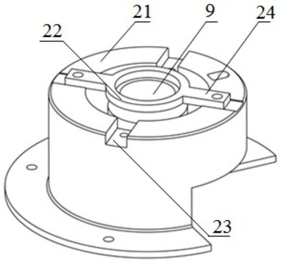
[0035] like figure 1 and figure 2 As shown, the mechanical pressing part 2 is used for pressing the thin-walled parts 9, including a support with a thin-walled part 9 placed inside and fixed on the base 1 by nuts, four through grooves 23 evenly distributed at the top and an annular gap at the bottom The sleeve 21 and the annular pressure block 22 disposed on the top of the support sleeve 21 , and both ends of the annular pressure block 22 are clamped into the two through grooves 23 ...


PUM


Abstract

The invention provides a magneto-rheological flexible fixture for thin-walled parts with arbitrary shapes, which is used for processing thin-walled parts with arbitrary shapes, including: a base; a mechanical pressing part, including thin-walled parts placed inside and fixed on the base by nuts , a support sleeve with four through grooves evenly distributed on the top and an annular notch at the bottom, and an annular pressure block set on the top of the support sleeve; a sealing cover, which is set on the top of the thin-walled parts; a liquid inlet hole, opened on the support sleeve The top edge of the machine; the mechanical clamping part includes a clamping support that is fixed on the base through a fixing nut and fits into the annular gap, and a fixed V-shaped block that is fixed on the base through a nut and is arranged on one side of the thin-walled part , a movable V-shaped block arranged on the other side of the thin-walled part, and a clamping nut that passes through the clamping support and the movable V-shaped block in turn and is used to adjust the position of the movable V-shaped block; and a drain pipe, one end of which is arranged on the support sleeve In the drain hole extending from the inner wall, the other end passes through the clamping support.

Description

technical field [0001] The invention belongs to the field of machining, in particular to a magnetorheological flexible clamp for thin-walled parts with arbitrary shapes. Background technique [0002] The processing of thin-walled parts in the field of mechanical processing is a difficult problem that cannot be overcome for a long time. Because of its light weight, material saving and compact structure, thin-walled parts have been increasingly widely used in various industrial sectors, especially some key parts. . However, the control of the machining accuracy of thin-walled parts has always been a difficult problem, because the thin-walled parts have poor rigidity and weak strength, are easily deformed during processing, and it is not easy to ensure the processing quality of the parts. How to improve the machining accuracy of thin-walled parts has always been a topic of concern in the industry. This patent can process thin-walled arbitrary-shaped frames, shells and other pa...

Claims


Application Information

Patent Timeline
Patent Type & Authority Patents(China)
IPC IPC(8): B23Q3/08
CPCB23Q3/086B23Q3/065
Inventor 江小辉吴坤张勇刘晓任斐
Owner UNIV OF SHANGHAI FOR SCI & TECH
Why Eureka
Try Eureka