

Backup wall reinforcement with t-type anchor
- Summary
- Abstract
- Description
- Claims
- Application Information
AI Technical Summary
Benefits of technology
Problems solved by technology
Method used
Image

Examples
first embodiment
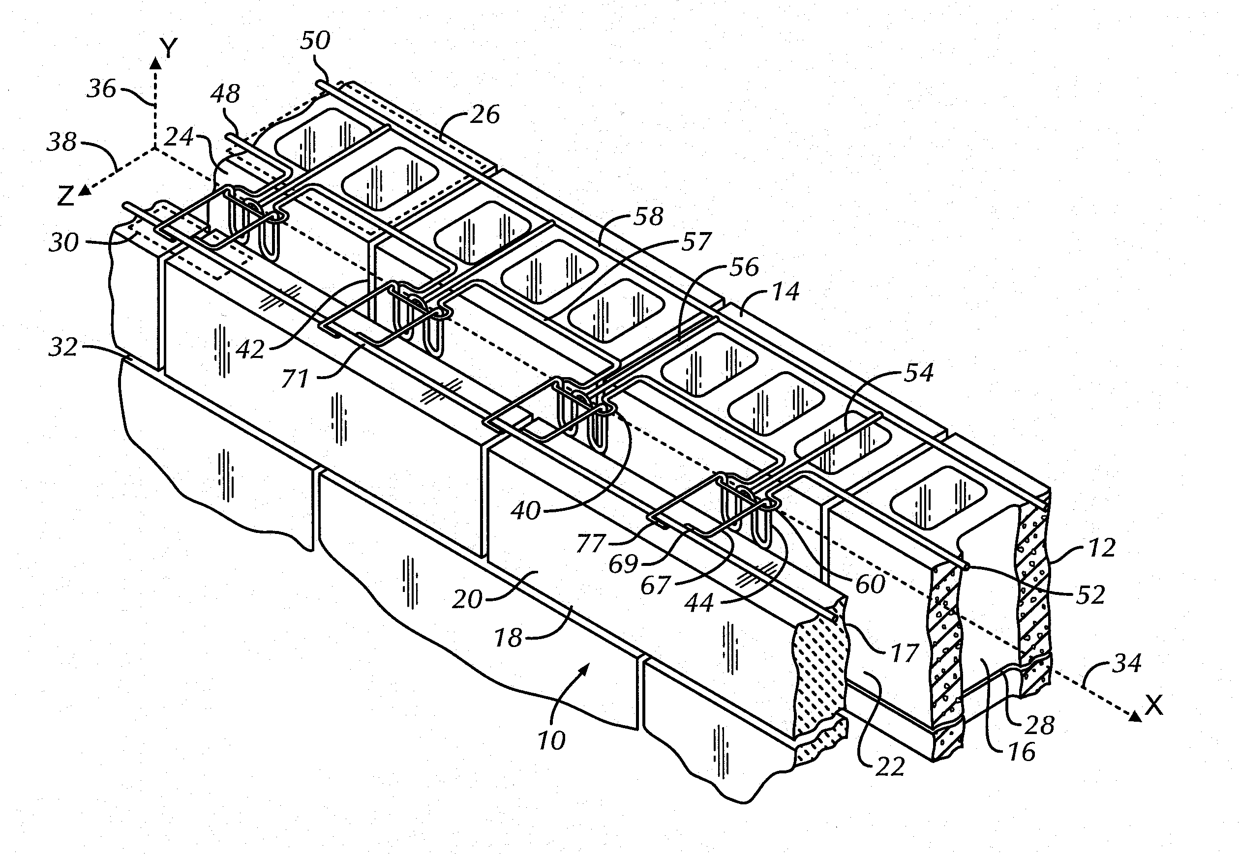
[0049]Referring now to FIG. 1 through 4 an anchoring system utilizing a backup wall reinforcement with T-type siderails is shown and is referred to generally by the numeral 10. In this embodiment, a masonry wall structure 12 is shown having a backup wall or exterior wythe 14 of masonry blocks 16 and a facing wall, exterior wall or veneer 18 of facing brick or stone 20. Between the backup wall 14 and the facing wall 18, a cavity 22 is formed, which cavity 22 extends outwardly from the interior surface 24 of backup wall 14. The backup wall 14 and the facing wall 18 have interior surfaces or sides 24 and 17, respectively that face the cavity 22.
[0050]In this embodiment, successive bed joints 26 and 28 are formed between courses of blocks 16 and the joints are substantially planar and horizontally disposed. Also, successive bed joints 30 and 32 are formed between courses of facing brick 20 and the bed joints are substantially planar and horizontally disposed. For each structure, the bed...
third embodiment
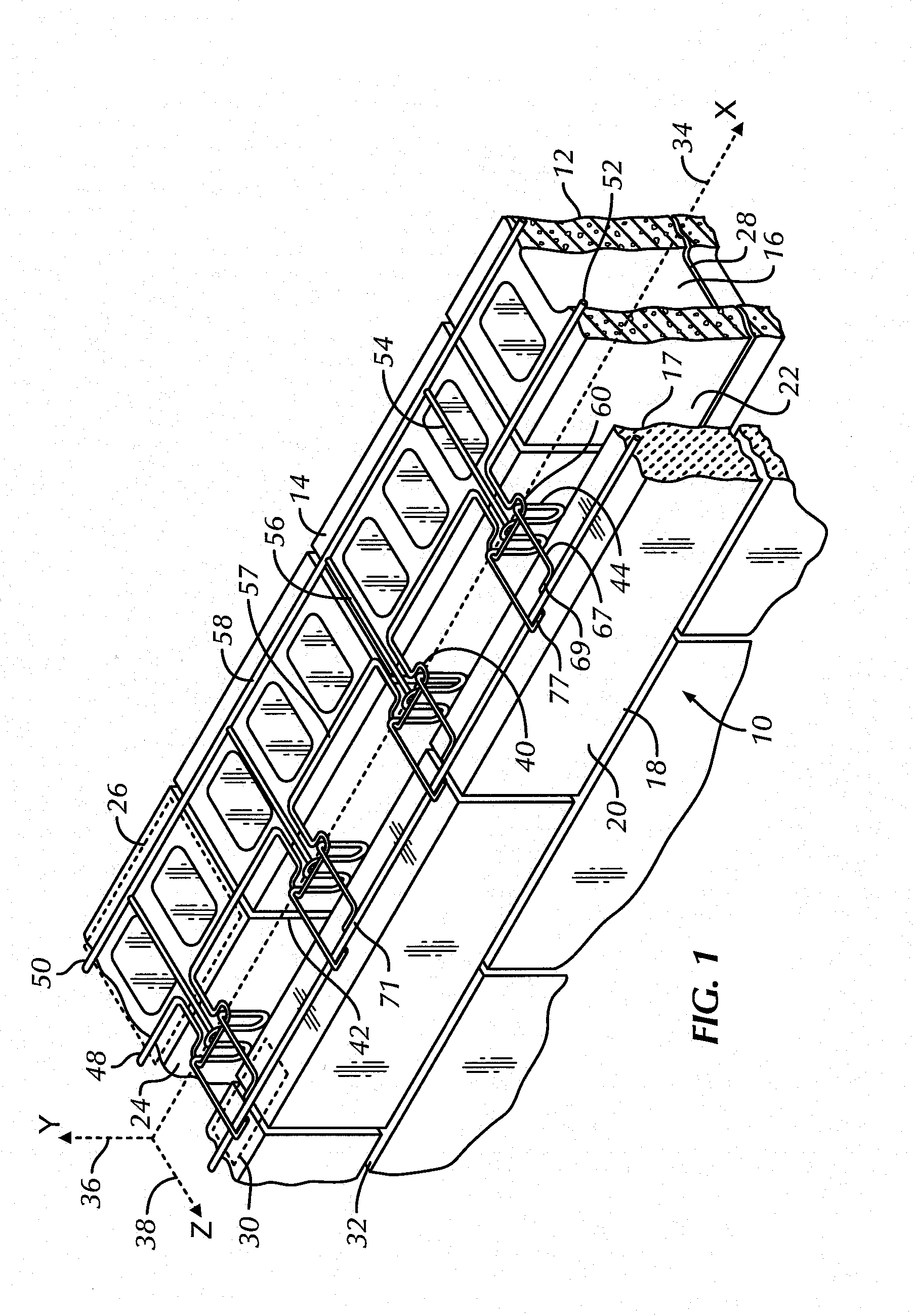
[0063]Referring now to FIGS. 8 and 9, a hybrid backup wall reinforcement having T-type anchors of this invention is shown and is referred to generally by the numeral 210. In this embodiment, a cavity wall structure is not shown, but is substantially similar to the cavity wall structure shown in FIG. 1. The anchoring system 210 includes a reinforcement device or wall reinforcement portion 248 with an integral anchor or wall anchor portion 260. The reinforcement device 248 is embedded in the bed joints and includes two side rails or wires 250, 252 which are parallel to each other. One or more intermediate wires 254, 256 are attached to the interior sides or surfaces of 257, 258 of the side rails 250, 252 and maintain the parallelism of the side rails 250, 252. The intermediate wires 254, 256 form a ladder configuration or optionally, a truss configuration (not shown). The longitudinal axis of the intermediate wires 254, 256 and the side rails 250, 252 is substantially similar to that ...
PUM
 Abstract
Description
Claims
Application Information