Method of Adjusting an Automatic Parking Brake

Active Publication Date: 2008-10-30
ROBERT BOSCH GMBH
View PDF3 Cites 0 Cited by
  • Summary
  • Abstract
  • Description
  • Claims
  • Application Information

AI Technical Summary

Benefits of technology

[0025]Additionally, the jacket advantageously comprises a second stop maki

Problems solved by technology

This can result in a loss of braking pr

Method used


Image

  • Method of Adjusting an Automatic Parking Brake
  • Method of Adjusting an Automatic Parking Brake
  • Method of Adjusting an Automatic Parking Brake

Examples


Embodiment Construction

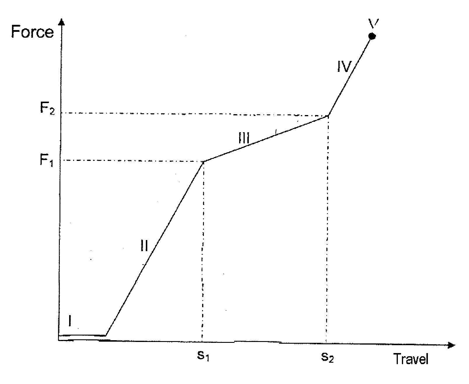
[0044]The object of the invention is to compensate for the thermal relaxation and hence the changes of volumes of the components of a brake device as it cools after the automatic parking brake has applied an immobilizing braking force to the vehicle to park it.

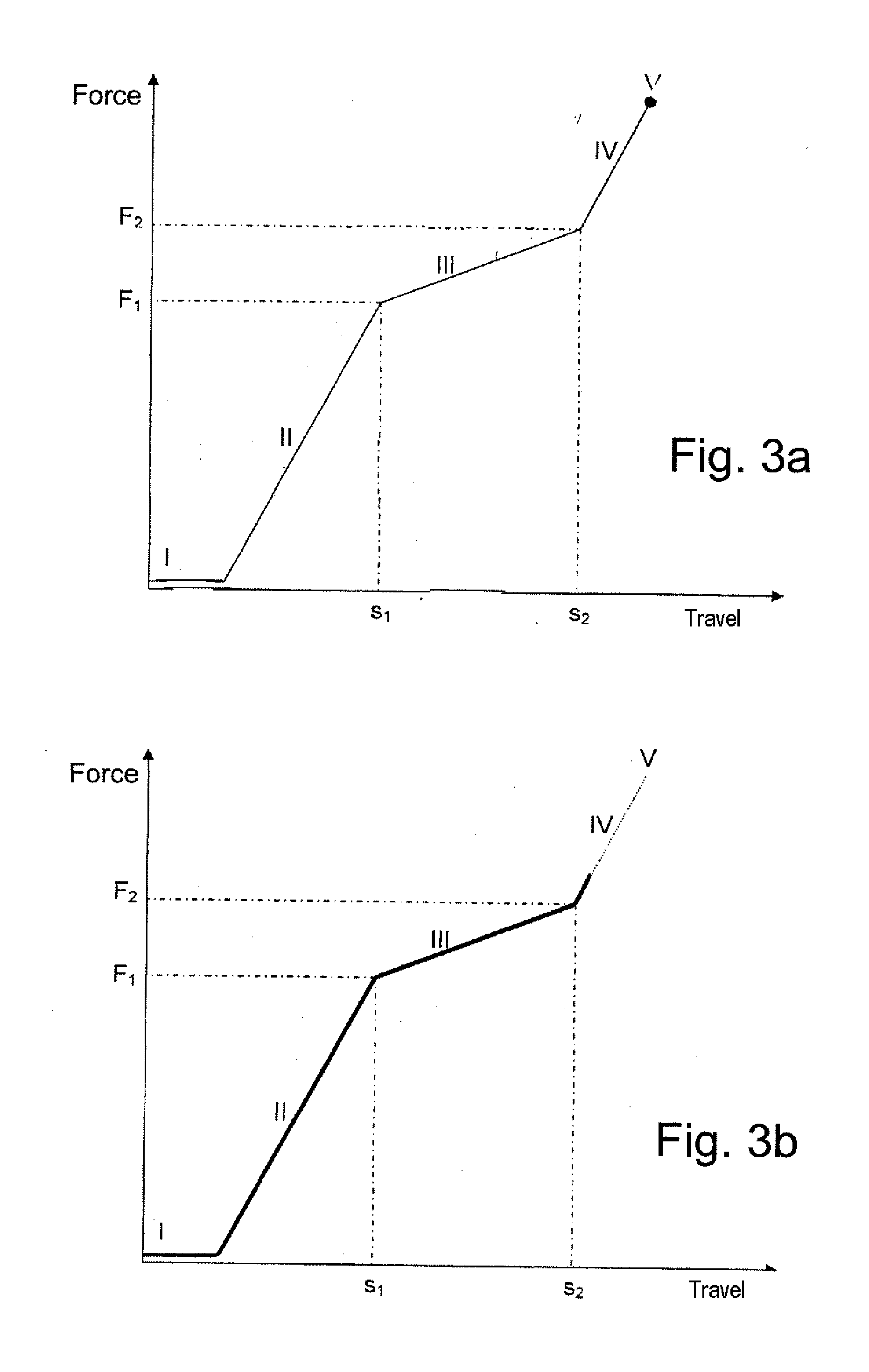
[0045]The method of the invention therefore requires applying only a very small force on top of the minimum vehicle-immobilizing force, so that only a small increase in the braking force is necessary to compensate, in a disk brake, for the loss of braking force during cooling or, in a drum brake, to compensate for the increase in the braking force.

[0046]Additionally, this device enables the applied braking force to be evaluated precisely.

[0047]The invention is applicable to an automatic parking brake system comprising a spring device capable of storing the system's braking energy.

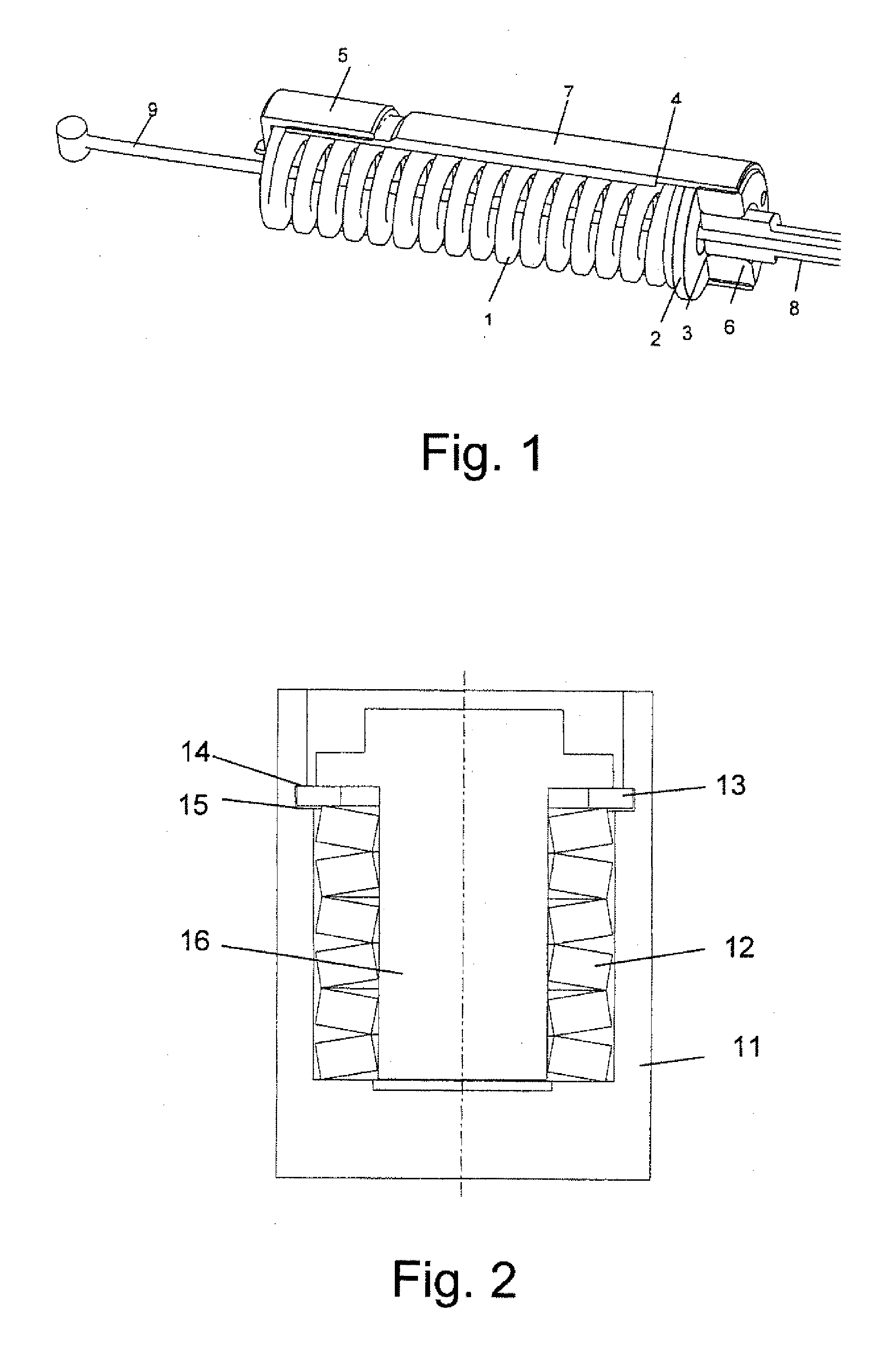
[0048]This is done with a washer acting on a spring element and able to move into abutment, for example as shown in FIG. 1 and as will be described b...


PUM


Abstract

The invention relates to a method of actuating an automatic parking brake for a vehicle, comprising a spring device, designed to absorb the actuating forces, situated in the actuating mechanism of a brake device. This method comprises at least the following steps: application of a preload to said spring device to a value situated in part IV of the operating characteristic, and adjustment of this preload to a level corresponding at least to a minimum braking force required for said vehicle.

Description

BACKGROUND OF THE INVENTION[0001]The invention relates to a method of compensating for the cooling of an automatic parking brake and a system employing this method.[0002]In a vehicle equipped with an automatic parking brake system, it is common practice for the brake to be brought into operation while the brake components are hot or even at a relatively high temperature. These components are therefore in an expanded state when the automatic parking brake system is applied.[0003]In a vehicle where the parking brake acts on a disk brake system, it is the disk and brake pads which are hot. Following application of the automatic parking brake, when the vehicle is at rest, the disk and brake pads cool down and shrink. The braking force decreases in step with the contraction of the pads and disk.[0004]This can result in a loss of braking pressure and can even release the vehicle. In some systems the braking force applied by the automatic parking brake takes this cooling into account and a...

Claims


Application Information

Patent Timeline
IPC IPC(8): F16D65/18
CPCF16D65/28F16D2121/14F16D2125/582F16D2123/00F16D2121/24F16D65/18F16D65/14
Inventor TRISTANO, NICOLACARUSO, CORRADOSCHEFZIK, MONIKA
Owner ROBERT BOSCH GMBH
Why Eureka
Try Eureka