Wind-powered main shaft forging method

A wind power spindle and flange technology, applied in the field of forging production, can solve the problems of low forging precision, complicated process, high energy consumption, etc., and achieve the effect of improving forging quality, improving work efficiency and saving forging time

Active Publication Date: 2012-12-05
JIANGSU LINGFEI FORGING
View PDF2 Cites 42 Cited by
  • Summary
  • Abstract
  • Description
  • Claims
  • Application Information

AI Technical Summary

Problems solved by technology

[0005] The technical problem to be solved by the present invention is to provide a forging method for wind power main shaft, which overcomes the problems of complicated process, high energy consumption, low efficiency, and low forging precision in the traditional forging method, and is conducive to the development trend of energy saving and emission reduction in the future

Method used


Image

  • Wind-powered main shaft forging method
  • Wind-powered main shaft forging method
  • Wind-powered main shaft forging method

Examples


Embodiment 1

[0032] Forging process of 1.5MW wind power main shaft, including steps:

[0033] a. The selected steel ingot must be the raw material of the steel ingot smelted by electric furnace smelting + LF (outside furnace refining) + VD (vacuum degassing) smelting process. The selected material is 34CrNiMo6, which conforms to DIN EN 10083-3, and guarantees that S≦0.15%, P≦0.20%, where [H]≦2.0ppm; [O]≦25ppm. For raw material steel ingots, the steelmaking plant conducts hot delivery of hot steel ingots according to the "Steel Ingot Hot Transport Regulations".

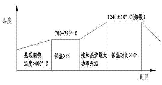
[0034] b, according to figure 2 , using hot steel ingots with a surface temperature greater than 400°C delivered by hot delivery from the steelmaking plant. The heating process is as follows: heat preservation at a furnace temperature of 700°C to 750°C for more than 3 hours, and then raise the temperature to 1240°C according to the maximum power of the heating furnace. ±10°C, keep warm for more than 10 hours;

[0035] c, accord...

Embodiment 2

[0043] The forging method of 2MW wind power main shaft, including steps:

[0044] a. The selected steel ingot must be the raw material of the steel ingot smelted by electric furnace smelting + LF (outside furnace refining) + VD (vacuum degassing) smelting process. The selected material is 42CrMo4, according to the requirements of the standard SEW550-1976, 0.40%≤C≤0.45%, Si≤0.40%, 0.60%≤Mn≤0.80%, S≤0.15%, P≤0.20%, 1.00%≤Cr≤1.20 %, 0.45%≤Ni≤0.60%, 0.18%≤Mo≤0.30%, where [H]≤2.0ppm; [O]≤25ppm.

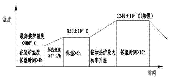
[0045] b, according to figure 1 For cold steel ingots, the cold steel ingot heating process will be adopted: put steel ingots with a surface temperature of less than 400°C into a hot furnace with a maximum charging furnace temperature lower than 400°C, keep them at the charging temperature for more than 4 hours, and then heat to 850±10°C, the temperature increase per hour is less than 60°C, and then keep warm for more than 6 hours, then raise the temperature to 1240±10°C according to the...


PUM


Abstract

The invention relates to a wind-powered main shaft forging method. The wind-powered main shaft forging method comprises the following steps of inspecting a material; heating the material; taking out a blank which is formed by annealing the material for the first time, pre-forging, upsetting, drawing and printing the blank, performing pre-forging to form the blank, and blanking; finally forging the blank to form a main shaft by annealing for the second time, forging a flange end on a hollow rotary worktable, and drawing the main shaft until a shaft body has forging size; performing re-crystallization normalized tempering thermal treatment by using a one-time thermal loading furnace after forging the wind-powered main shaft; roughly turning the wind-powered main shaft and detecting flaws through ultrasonic wave; hardening and tempering the wind-powered main shaft, and performing nondestructive inspection and physical and chemical inspection on the wind-powered main shaft; finely turning the wind-powered main shaft; and packaging the wind-powered main shaft. The wind-powered main shaft forging method provided by the invention has the characteristics that the efficiency is high, the energy is saved, the cost is reduced, and the forging quality is improved.

Description

[0001] technical field [0002] The invention relates to a forging method of a wind power main shaft, which belongs to the technical field of forging production. Background technique [0003] At present, with the rapid development and maturity of the wind power industry in my country, the forging output of wind power spindles has been greatly improved in China. Nowadays, the manufacturing development trend of large-scale MW wind power main shafts is towards large-scale development. The weight of forgings is getting heavier and the quality requirements of forgings are getting higher and higher. Higher requirements are put forward for the design and manufacture of wind power main shafts and forging production methods. Require. [0004] The current mainstream wind power spindle forging method still adopts the traditional forging process and post-forging heat treatment process. There are many disadvantages in this forging method: the traditional forging method requires many ti...

Claims


Application Information

Patent Timeline
Patent Type & Authority Applications(China)
IPC IPC(8): B21J5/08B21K1/06C21D1/18C21D1/28C21D9/00
Inventor 钱飞杨晓明殷勇锋
Owner JIANGSU LINGFEI FORGING
Why Eureka
Try Eureka