Horizontal linear vibrator

a linear vibrator and horizontal technology, applied in the direction of dynamo-electric machines, electrical equipment, magnetic circuit shapes/forms/construction, etc., can solve the problems of reducing the lifetime of the vibration generating device, reducing the efficiency wasting time on vibration generating devices. achieve the effect of maintaining the lifetime and response characteristics of the linear vibrator, linear vibrating and improving the quantity of vibration

Inactive Publication Date: 2011-03-17
MPLUS
View PDF2 Cites 43 Cited by
  • Summary
  • Abstract
  • Description
  • Claims
  • Application Information

AI Technical Summary

Benefits of technology

[0013]The present invention has been made in an effort to provide a horizontal linear vibrator that has a horizontal vibration structure capable of making a linear vibrator slim and improving vibration quantity thereof while maintaining lifetime and response characteristics of the linear vibrator and can control motion displacement of the vibrator and improve durability thereof.

Problems solved by technology

However, the vibration generating device having such a form causes mechanical friction and electrical spark and abrasion while the brush passes through a gap between segments of the commutator and thus, generates foreign materials such as black powder, thereby reducing the lifetime of the vibration generating device.
In addition, when the vibration generating device is applied with voltage, it takes much time to reach targeted vibration quantity due to the rotational inertia thereof.
As a result, the vibration generating device does not implement the vibration that is in particular suitable for the touch screen mobile phone.
In particular, there is a problem in that this runs counter to the trend of the miniaturization and slimness of the mobile phone.

Method used


Image

  • Horizontal linear vibrator
  • Horizontal linear vibrator
  • Horizontal linear vibrator

Examples


Embodiment Construction

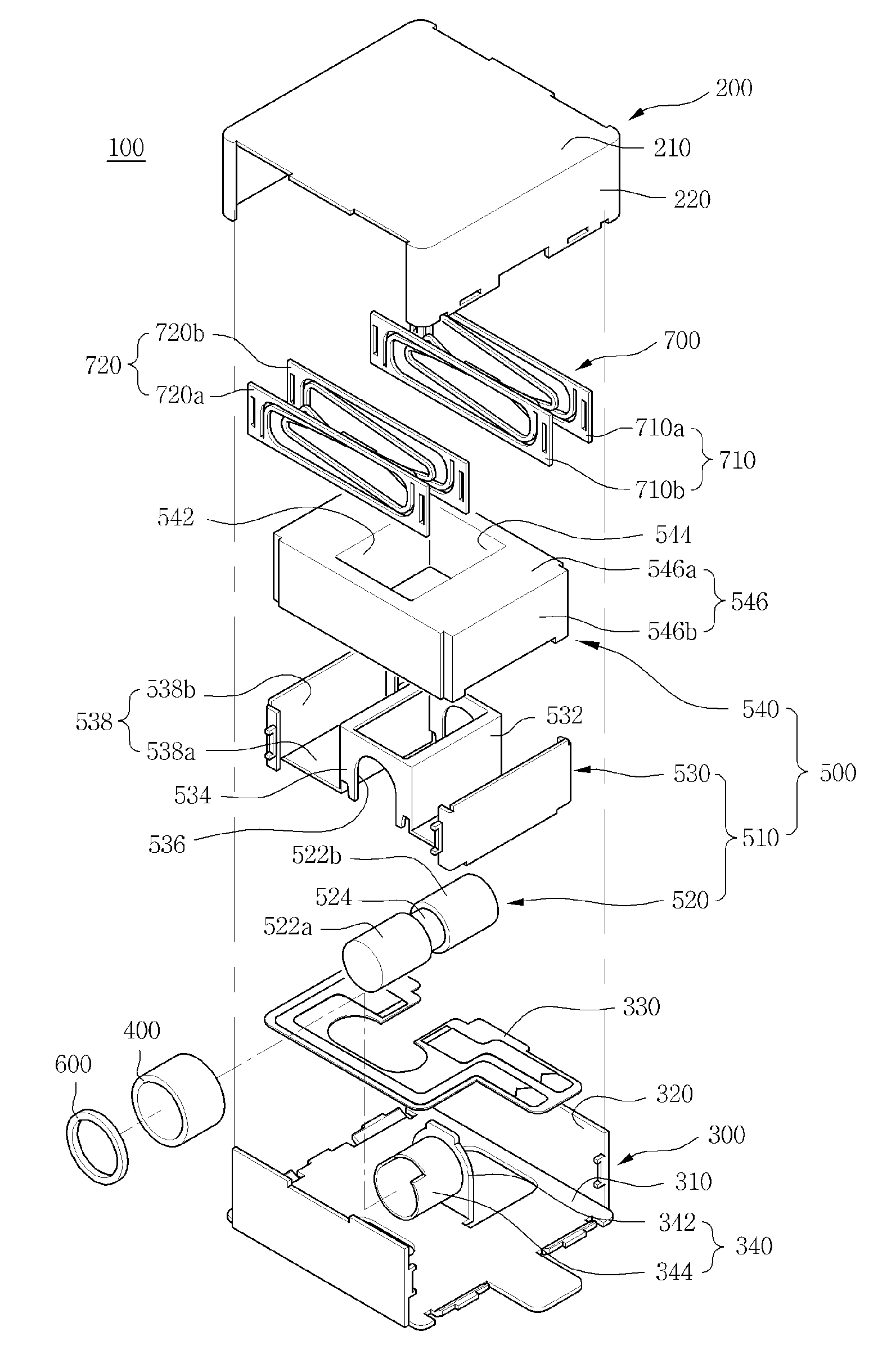
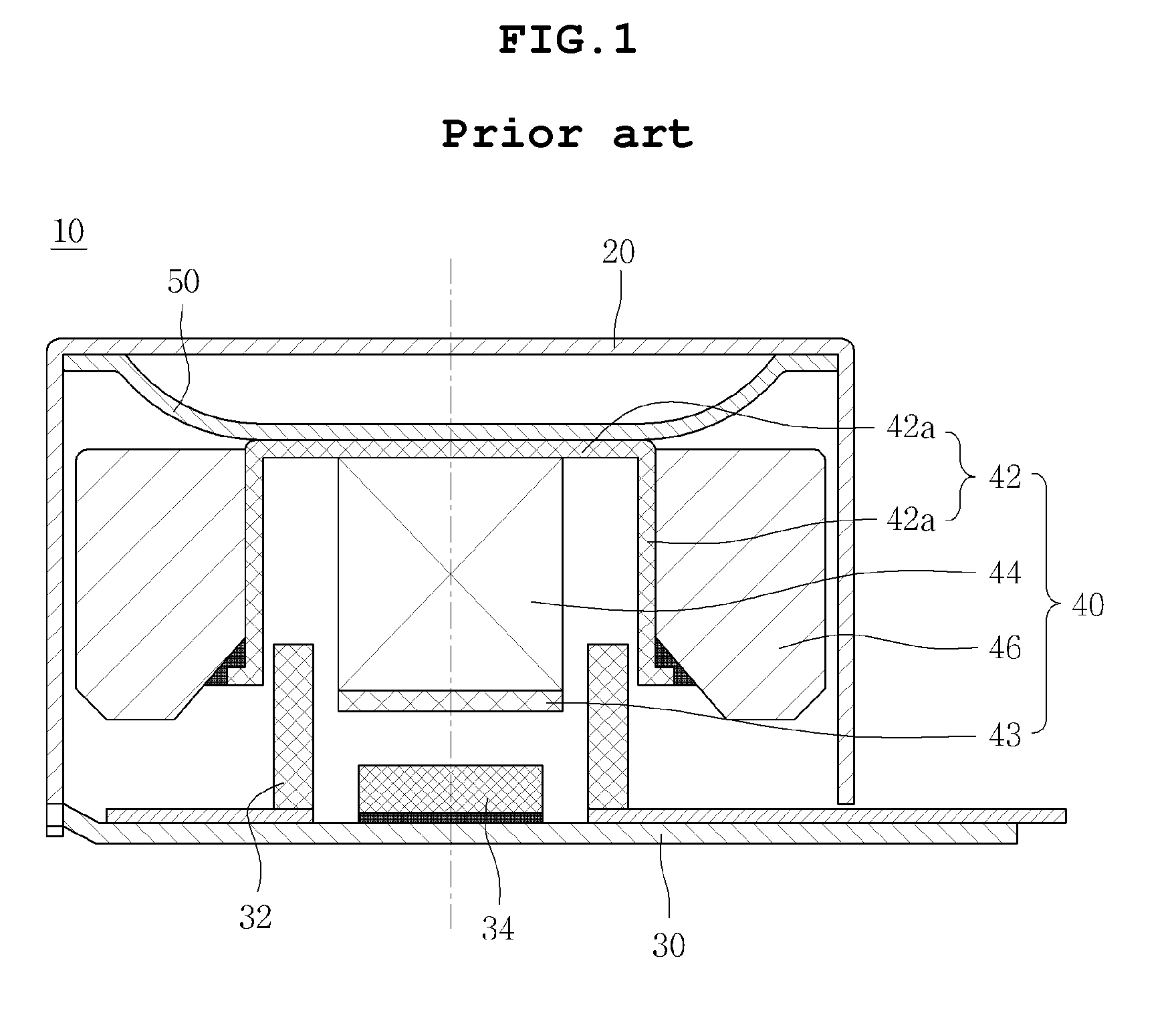
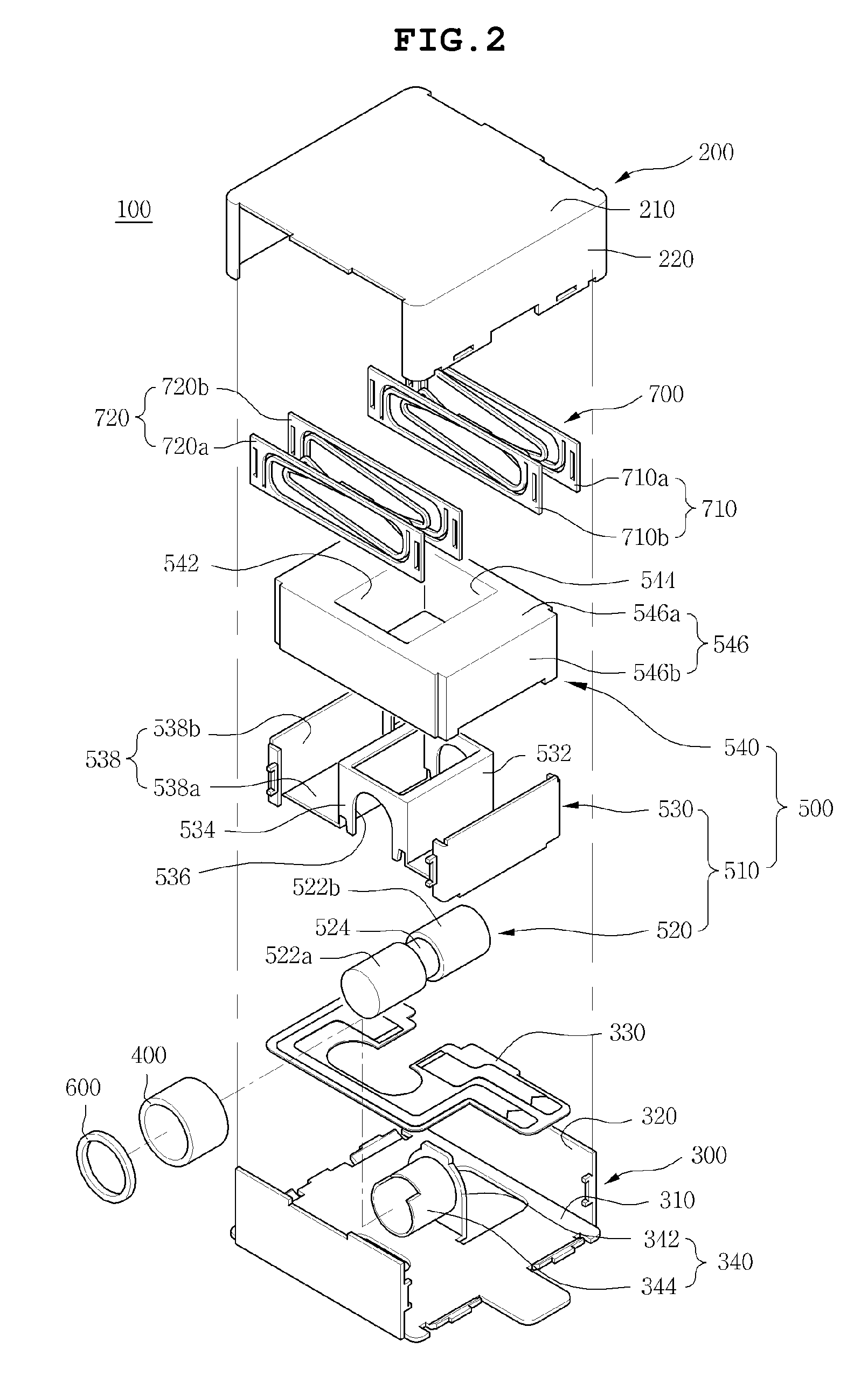
[0031]The features and advantages of the present invention will be more obvious from the following description with reference to the accompanying drawings.

[0032]Terms or words used in the specification and claims herein should be not construed as a general and lexical meaning and should be construed as the meaning and concept meeting the technical idea of the present invention based on a principle that the present inventors can properly define the concepts of terms in order to elucidate their own invention in the best method.

[0033]The above and other objects, features and advantages of the present invention will be more clearly understood from the following detailed description taken in conjunction with the accompanying drawings. In the specification, in adding reference numerals to components throughout the drawings, it is to be noted that like reference numerals designate like components even though components are shown in different drawings. Further, in describing the present inv...


PUM


Abstract

Disclosed herein is a horizontal linear vibrator. The horizontal linear vibrator includes: a case and a bracket that are assembled with each other to form an inner space; a hollow coil that is installed in the case or the bracket; a vibrator that includes a magnetic field unit including one or more magnet disposed to penetrate through the inside of the hollow coil and a yoke formed to enclose the hollow coil and the magnets to generate magnetic field and a weight mounted in the magnetic field unit; a buffer member that is provided between the hollow coil and the yoke; and a spring member whose one end is fixed to the case or the bracket and other end is fixed to the vibrator and elastically supports the vibrator so as to horizontally move the vibrator. Thereby, there is provided the horizontal linear vibrator that has a horizontal vibration structure capable of maintaining the lifetime and response characteristics of the horizontal linear vibrator, implementing the sliminess thereof, increasing the vibration quantity thereof while controlling the motion displacement and improving the durability thereof.

Description

CROSS REFERENCE TO RELATED APPLICATION[0001]This application claims the benefit of Korean Patent Application No. 10-2009-0085977, filed Sep. 11, 2009, entitled “HORIZONTAL LINEAR VIBRATOR”, which is hereby incorporated by reference in its entirety into this application.BACKGROUND OF THE INVENTION[0002]1. Technical Field[0003]Currently, a vibration generating device, which is one of several signal receiving indicating devices used in communication devices, such as cellular phones, converts electric energy into mechanical vibration by the use of a principle of generating electromagnetic force. That is, the vibration generating device has been mounted in the mobile phone to be used to notify mute signal reception.[0004]2. Description of the Related Art[0005]In recent, as the use of the mobile phone in a touch screen scheme is rapidly increased, the vibration generating device has been widely adopted for a touch screen mobile phone. Since the use frequency of the vibration generating de...

Claims


Application Information

Patent Timeline
Patent Type & Authority Applications(United States)
IPC IPC(8): H02K33/00
CPCH02K33/18H02K1/17H02K1/223H02K1/265
Inventor LEE, JEE SUNGPARK, SEOK JUNCHOI, JUN KUN
Owner MPLUS
Why Eureka
Try Eureka