Vibration device

一种振动装置、弹性部件的技术,应用在机电装置、利用振动的流体、电动组件等方向,能够解决弹力减少、振动量减少等问题

Inactive Publication Date: 2010-10-13
EM TECHNOLOGY CO LTD
View PDF5 Cites 2 Cited by
  • Summary
  • Abstract
  • Description
  • Claims
  • Application Information

AI Technical Summary

Problems solved by technology

[0011] However, if the counterweight 50 becomes thicker, the size of the magnet 40 becomes smaller; The amount of vibration generated by the interaction of the
[0012] Also, if the weight is expanded in the circumferential direction to increase the amount of vibration, the length of the leaf spring 60 formed between the weight 50 and the spring holder 70 is reduced , resulting in a decrease in the elastic

Method used


Image

  • Vibration device
  • Vibration device
  • Vibration device

Examples


no. 1 approach

[0036] Hereinafter, a vibration device according to the first embodiment of the present invention will be described in detail.

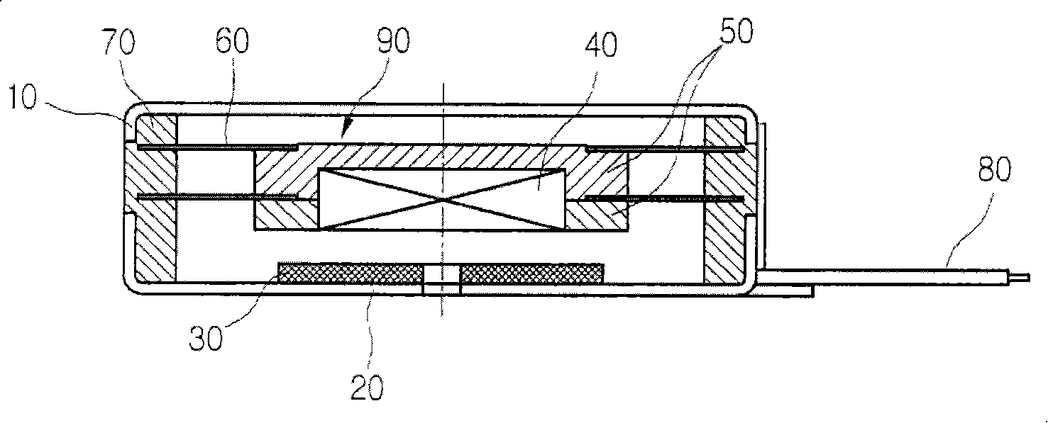
[0037] image 3 Is a cross-sectional view of the vibration device according to the first embodiment of the present invention, Figure 4 Is a cross-sectional view showing another example of the vibration device according to the first embodiment of the present invention, Figure 5 Is a perspective view showing an example of the elastic member used in the vibration device of the present invention, Image 6 It is a side view showing another example of the elastic member used in the vibration device of the present invention.

[0038] Such as image 3 As shown, the vibration device according to the first embodiment of the present invention includes an upper shell 110 and a lower shell 120 combined with each other; a magnetic force generating part 130 formed in the middle of the upper surface of the lower shell 120; and a magnetic flux passing through the magnetic...

no. 2 approach

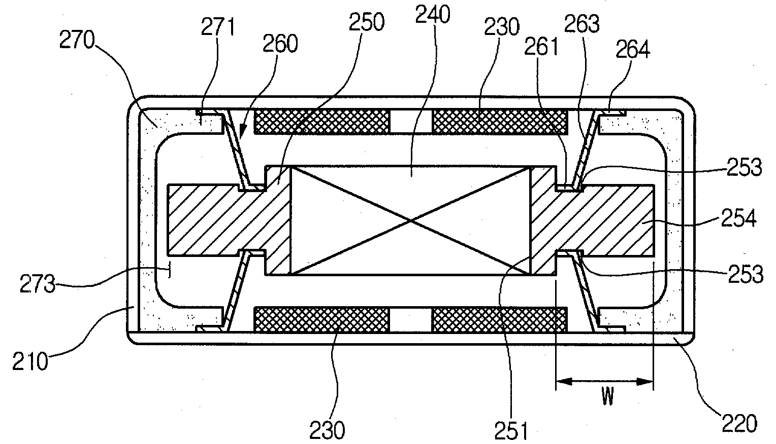
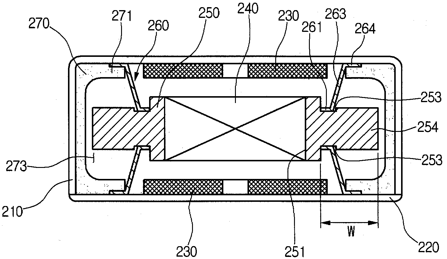
[0058] Figure 7 It is a cross-sectional view of a vibration device according to the second embodiment of the present invention.

[0059] Such as Figure 7 As shown, the vibration device according to the second embodiment of the present invention includes an upper shell 210 and a lower shell 220 combined with each other; a magnetic force generating part 230 formed in the middle of the upper shell 210 and the lower shell 220; A magnet 240 that generates attraction or repulsion by the interaction of magnetic flux. The magnet 240 is formed on each magnetic force generating part 230. The magnet 240 is mounted on the magnet 240 and forms an integral weight 250. The magnetic force generating part 230 and the magnet 240 The counterweight 250 increases the amount of vibration of vertical movement; the elastic member 260 is combined with the upper and lower surfaces of the counterweight 250 and extends on the upper and lower parts of the counterweight 250 to elastically support the counter...

no. 3 approach

[0068] Picture 9 Is an enlarged three-dimensional view showing the vibrating device with a sound emitting function according to the third embodiment of the present invention, and Picture 10 It is a cross-sectional view of a vibrating device with a sound emitting function according to the third embodiment of the present invention.

[0069] According to the vibration device of the third embodiment of the present invention, in addition to the basic vibration function, it also has a sound-generating function.

[0070] Such as Picture 9 with 10 As shown, the vibration device according to the third embodiment of the present invention includes a shell 350; an end plate 355 formed on one side of the shell 350 for providing external power; and an end plate 355 located above the shell 350 for generating sound. A vibrating plate 370; a voice coil 330 under the vibrating plate 370 for generating an electric field; a magnetic force generator 340 installed under the voice coil 330; a three-dim...


PUM


Abstract

Disclosed is a vibration device in which an elastic unit is formed on upper and / or lower surface of a weight, and the weight for generating vibration is extended in a circumferential direction. Also, a vibration device with a sound function, which gives an improved vibrating amount by making a larger magnetic force generating. unit to be supported by elastic units, is also disclosed. Thus, the vibration device may be made in a smaller size, and therefore it enables miniaturization of a mobile communication terminal in which such vibration device is usually mounted.

Description

technical field [0001] The present invention relates to a vibrating device, more particularly, to a vibrating device that increases the amount of vibration by applying a three-dimensional elastic member, increasing the size of a counterweight supported by the elastic member, and to a vibrating device, It increases the amount of vibration by making a larger magnetic force generating member, which is supported by an elastic member. Background technique [0002] Generally, mobile communication terminals, such as portable phones, pagers and PDAs, use vibrating devices to send a vibration to the user in addition to the sound of a ringtone when receiving a message or a call. [0003] figure 1 is a cross-sectional view of a conventional vibrating device, while figure 2 is a perspective view of a leaf spring used in a conventional vibrating device. [0004] like figure 1 Shown, conventional vibration device comprises a lower case 20, a coil 30 installed in the middle part of lo...

Claims


Application Information

Patent Timeline
Patent Type & Authority Patents(China)
IPC IPC(8): H02K7/065B06B1/04H02K33/16
CPCH02K33/16B06B1/045H02K7/065
Inventor 金尚真
Owner EM TECHNOLOGY CO LTD
Why Eureka
Try Eureka