
Horizontal laying machine for ceramic tiles

A technology of tile machine and ceramic tile, which is applied in the direction of construction and building structure, can solve the problems of difficult adsorption of tiles, accidents, different sizes and specifications of tiles, etc., and achieves the effects of low cost, increased vibration and convenient operation.

Inactive Publication Date: 2019-03-22
海门市大树电动工具厂
View PDF4 Cites 2 Cited by
  • Summary
  • Abstract
  • Description
  • Claims
  • Application Information

AI Technical Summary

Problems solved by technology

However, the existing tiling machines often rely on only one suction cup to absorb tiles, which is not firm and easy to cause accidents. At the same time, tiles are of different sizes and specifications, and it is often difficult for a suction cup to absorb tiles that are too large.

Method used


Image

  • Horizontal laying machine for ceramic tiles

Examples


Embodiment Construction

[0015] The present invention will be further described below in conjunction with the accompanying drawings.

[0016] In order to make the object, technical solution and advantages of the present invention clearer, the present invention will be further described in detail below in conjunction with the accompanying drawings and specific embodiments. It should be understood that the specific embodiments described here are only used to explain the present invention, and are not intended to limit the present invention.

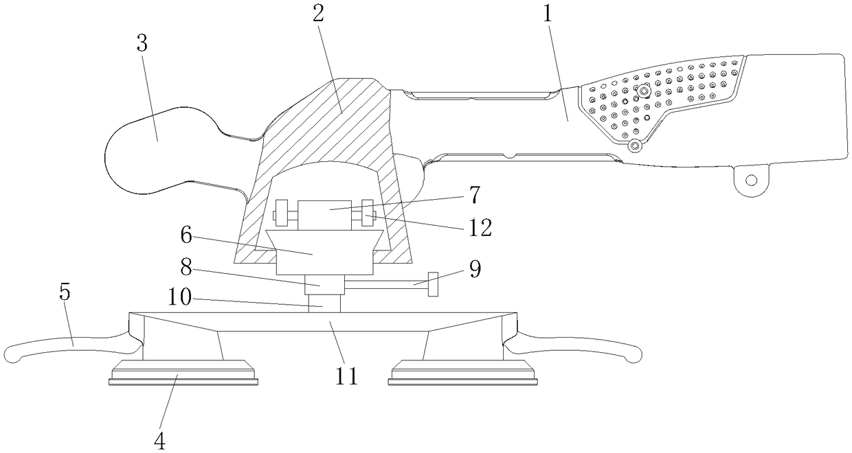
[0017] see figure 1 , a tile tiling machine, comprising a main handle 1, a drive cavity 2, an auxiliary handle 3, a rubber suction cup 4, a suction cup control handle 5, a vibration block 6 and a vibration motor 7, and the drive cavity 2 is arranged on the main handle 1 and the auxiliary handle Between the handles 2, the main handle 1 is cylindrical with a slightly thinner front end and a thicker rear end. A vibrating motor 7 is arranged inside the driving cavity ...


PUM


Abstract

The invention discloses a horizontal laying machine for ceramic tiles. The horizontal laying machine comprises a main handle, a driving cavity, an auxiliary handle, a rubber suction cup, a suction cupcontrol handle, a vibration block and a vibration motor. The driving cavity is formed between the main handle and the auxiliary handle, the main handle is in the shape of a cylinder with the front end slightly thinner than the rear end, the vibration motor is arranged in the driving cavity, the vibration block is arranged at the lower end of the vibration motor, and an opening corresponding to the vibration block is formed in the lower end wall of the driving cavity. The lower end vibration block penetrates through the opening to the outside of the driving cavity, a shaft sleeve is fixedly arranged at the lower end of the vibration block, a fastening bolt is arranged outside the shaft sleeve, a rotary shaft is arranged in the shaft sleeve, a cross rod is fixedly arranged at the lower endof the rotary shaft, rubber suction cups are arranged at the left end and the right end of the cross rod, and suction cup control handles are arranged on the rubber suction cups. The vibration motor is embedded into the vibration block. According to the Horizontal laying machine for ceramic tiles for the ceramic tiles, the design of double rubber suction cups is adopted, the horizontal laying machine can adapt to the ceramic tiles of different sizes and specifications, the vibration amount of the vibration motor can be increased by arranging two eccentric blocks, and better vibration tiling work is achieved.

Description

technical field [0001] The invention relates to the technical field of electric tools, in particular to a ceramic tile tiling machine. Background technique [0002] For many years, the tile laying of building floors and slabs has been done manually. Manual laying needs to be laid out first, and then aligned, moved closer and compacted piece by piece. The labor intensity is high and the construction efficiency is low. Higher requirements. Traditionally, when laying tiles, the ground needs to be leveled, and after the tiles are laid, they have to be tapped tightly with a hammer, which is very laborious and the laying efficiency is low. In order to simplify the ceramic tile laying process and reduce the labor intensity of the operator, there have been special equipment for tile laying. However, the existing tiling machines often only rely on one suction cup to absorb tiles, which is not firm and easy to cause accidents. At the same time, tiles have different sizes and specifi...

Claims


Application Information

Patent Timeline
Patent Type & Authority Applications(China)
IPC IPC(8): E04F21/22
CPCE04F21/22
Inventor 卢小双
Owner 海门市大树电动工具厂
Learn More