Suspension control input apparatus

An input device and suspension control technology, applied in the input/output process of data processing, instruments, electrical digital data processing, etc., can solve the problems of large size and discontinuous detection signal, improve the signal-to-noise ratio and avoid discomfort , the effect of reducing the number of light sources

Inactive Publication Date: 2016-02-17
INTEGRATED CRYSTAL TECH +1
View PDF3 Cites 2 Cited by
  • Summary
  • Abstract
  • Description
  • Claims
  • Application Information

AI Technical Summary

Problems solved by technology

[0010] The purpose of the present invention is to address the deficiencies in the prior art, and propose a suspension control input device, which mainly solves the problems of large volume and discontinuous detection signals in the existing suspension control input device

Method used


Image

  • Suspension control input apparatus
  • Suspension control input apparatus
  • Suspension control input apparatus

Examples


Embodiment 1

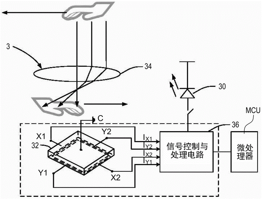
[0108] image 3 It is a structural diagram of the floating control input device according to the first embodiment of the present invention. image 3 The levitation control input device 3 shown includes an infrared light emitting diode 30, a two-dimensional position sensor (Position Sensitive Device, referred to as PSD) 32, an imaging module 34 located above the position sensor 32, and a Signal control and processing circuit 36. The output electrodes X1, X2, Y1, and Y2 of the position sensor 32 are drawn from the four sides of the position sensor 32. The imaging module 34 may include an optical lens or a mechanical structure.

[0109] In the levitation control input device 3, the signal control and processing circuit 36 ​​controls the pulse timing and intensity of the infrared light pulses emitted by the infrared light emitting diode 30. The position sensor 32 converts the ambient background light and the infrared reflected light pulse formed by the object reflected infrared ligh...

Embodiment 2

[0140] Picture 8 It is a structural diagram of the floating control input device according to the second embodiment of the present invention. The levitation control input device 4 of this embodiment includes an infrared light-emitting diode 40, a two-dimensional position sensor 42 capable of distinguishing the orientation, an imaging module 44 located above the position sensor 42, and a signal control and processing circuit 46. The output electrodes X1, X2, Y1, and Y2 of the position sensor 42 are drawn from the four corners of the position sensor 42.

[0141] In the floating control input device 4, the signal control and processing circuit 46 controls the pulse timing and intensity of the infrared light pulse emitted by the infrared light-emitting diode 40; the position sensor 42 converts the ambient background light and the infrared reflected light pulse passing through the imaging module 44 into Electric signal I X1 , I X2 , I Y1 , I Y2 . The signal control and processing c...


PUM


Abstract

The present invention provides a suspension control input apparatus, so as to solve the problems that an existing suspension control input apparatus is large in volume and detection signals are not continuous. The suspension control input apparatus comprises an infrared light emitting diode, a position sensor, and a signal control and processing circuit. The signal control and processing circuit is electrically connected to the infrared light emitting diode, and the signal control and processing circuit drives the infrared light emitting diode and controls timing of infrared light pulses of the infrared light emitting diode. The infrared light pulses are used to illuminate an object; reflected infrared light of the object is projected on the position sensor; and the position sensor converts the received reflected infrared light and ambient background light into a corresponding electrical signal. The signal control and processing circuit synchronously receives and processes the electrical signal according to the timing of the infrared light pulses. The signal control and processing circuit converts a light pulse signal of infrared reflection into a digital signal, and transmits the digital signal to a microprocessor to calculate a distance, a position, a movement direction and a movement speed of the object. The apparatus can be applied to suspension control of a portable electronic product.

Description

Technical field [0001] The invention relates to an input device, in particular to an input device which can be applied to the suspension control of a portable electronic product. Background technique [0002] The floating control input device is a human-computer interaction device that can detect signals such as the relative position, movement speed, and movement direction of the control gesture without touching the surface of the device. These detected control gestures can be input as control instructions to an electronic product equipped with the device, such as page left, page right, page down, page up, and click. The floating control input device has more and more extensive applications in portable electronic products, such as smart phones and tablet computers. [0003] The traditional floating control input device usually uses the camera to capture the image, and the image obtained by the camera is processed and analyzed by software to identify the various control actions of ...

Claims


Application Information

Patent Timeline
Patent Type & Authority Applications(China)
IPC IPC(8): G06F3/042
Inventor 李文岑黄进文侯博闻来新泉何惠森关会丽
Owner INTEGRATED CRYSTAL TECH
Why Eureka
Try Eureka