Multifunctional compression tester

A compression test and multi-functional technology, applied in the direction of applying stable tension/pressure to test the strength of materials, measuring devices, instruments, etc., can solve the problem that the expansion and contraction speed cannot be adjusted accurately in real time, and the screw compression extrusion device cannot be tested and measured. Real-time pressure, torque and power parameters real-time measurement and other issues

Active Publication Date: 2016-03-09
BEIJING TECHNOLOGY AND BUSINESS UNIVERSITY
View PDF7 Cites 9 Cited by
  • Summary
  • Abstract
  • Description
  • Claims
  • Application Information

AI Technical Summary

Problems solved by technology

This compression test equipment has the following disadvantages: (1) it can only test and measure the piston compression process, but cannot test and measure the screw compression extrusion device; (2) based on the working principle of the hydraulic cylinder, its expansion and contraction speed cannot be measured. Real-time and accurate adjustment, so it is impossible to test and measure the compression process with variable compression speed; (3) It is impossible to test compression chambers / compression cylinders of different specifications on the same equipment; (4) It is impossible to measure the real-time pressure during the compression process , torque and power parameters for real-time measurement

Method used


Image

  • Multifunctional compression tester
  • Multifunctional compression tester
  • Multifunctional compression tester

Examples


Embodiment Construction

[0025] Preferred embodiments of the present invention are described below with reference to the accompanying drawings. Those skilled in the art should understand that these embodiments are only used to explain the technical principle of the present invention, and are not intended to limit the protection scope of the present invention. On the premise of not changing the basic principles of the present invention, those skilled in the art can combine, split, etc. related features. For example, although the screw support and the bearing seat fixed on the lead screw support are described as independent parts in this application, the screw support and the bearing seat can obviously be set as one, and this modification does not Changes to the principle of the present invention will therefore also fall within the protection scope of the present invention.

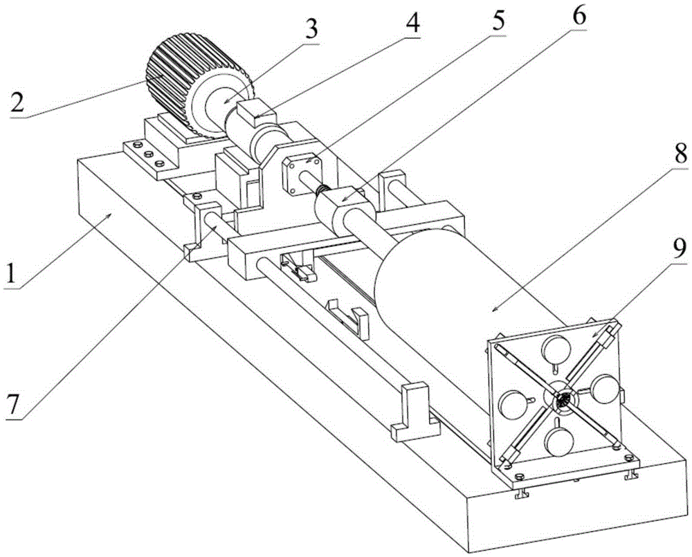
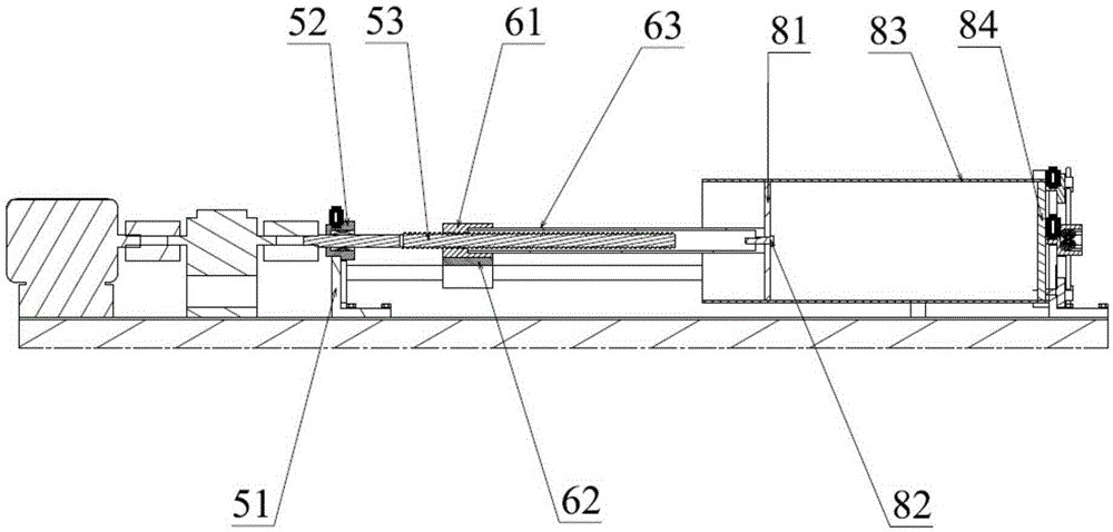
[0026] see first figure 1 and 2 , the multifunctional compression testing machine includes a platform 1 on which other relevan...


PUM


Abstract

The invention relates to testing equipment, and particularly provides a multifunctional compression tester which aims at solving the problems that for an existing compression tester, screw-type compression cannot be measured, and the compression speed cannot be regulated in real time. For solving the problems, the compression tester comprises a motor arranged on a platform, a lead screw assembly, a translational moving assembly and a compression barrel assembly; the lead screw assembly comprises a lead screw support, a bearing seat fixed on the lead screw support and a lead screw penetrating through the bearing seat, and the lead screw is driven by the motor to rotate; the translational moving assembly comprises a transducer block spirally arranged on the lead screw in a sleeving mode and a sliding wing slidably supporting the transducer block; the compression barrel assembly comprises a compression barrel and a compression device arranged in the compression barrel, and the compression device is driven by the transducer block or the lead screw. According to the tester, due to the fact that the motor is adopted as a power source and the lead screw assembly is combined with the translational moving assembly, not only can piston-type compression be measured, but also screw-type compression can be measured, and the stretch speed can be accurately regulated in real time.

Description

technical field [0001] The invention relates to testing equipment, and specifically provides a multifunctional compression testing machine. Background technique [0002] The traditional compression test equipment for agricultural products adopts the method of measuring the compression force sensor of the hydraulic cylinder to perform the compression test. This compression test equipment has the following disadvantages: (1) it can only test and measure the piston compression process, but cannot test and measure the screw compression extrusion device; (2) based on the working principle of the hydraulic cylinder, its expansion and contraction speed cannot be measured. Real-time and accurate adjustment, so it is impossible to test and measure the compression process with variable compression speed; (3) It is impossible to test compression chambers / compression cylinders of different specifications on the same equipment; (4) It is impossible to measure the real-time pressure durin...

Claims


Application Information

Patent Timeline
Patent Type & Authority Applications(China)
IPC IPC(8): G01N3/08G01N3/02
CPCG01N3/02G01N3/08
Inventor 黄志刚高东明翁云宣李杰
Owner BEIJING TECHNOLOGY AND BUSINESS UNIVERSITY
Why Eureka
Try Eureka