
Built-out spring universal spray pump
A spray pump and pump body technology, applied in the field of spring external universal spray pump, can solve the problems of complex structure, affecting the use effect, unhygienic and other problems, and achieve the effect of convenient use, ingenious design and simple structure
- Summary
- Abstract
- Description
- Claims
- Application Information
AI Technical Summary
Problems solved by technology
Method used
Image

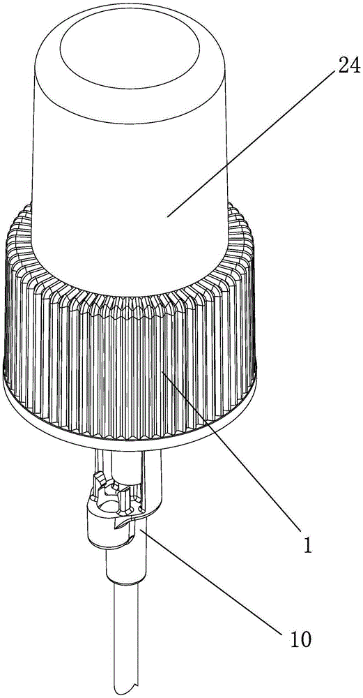
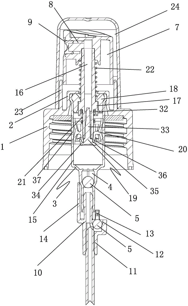
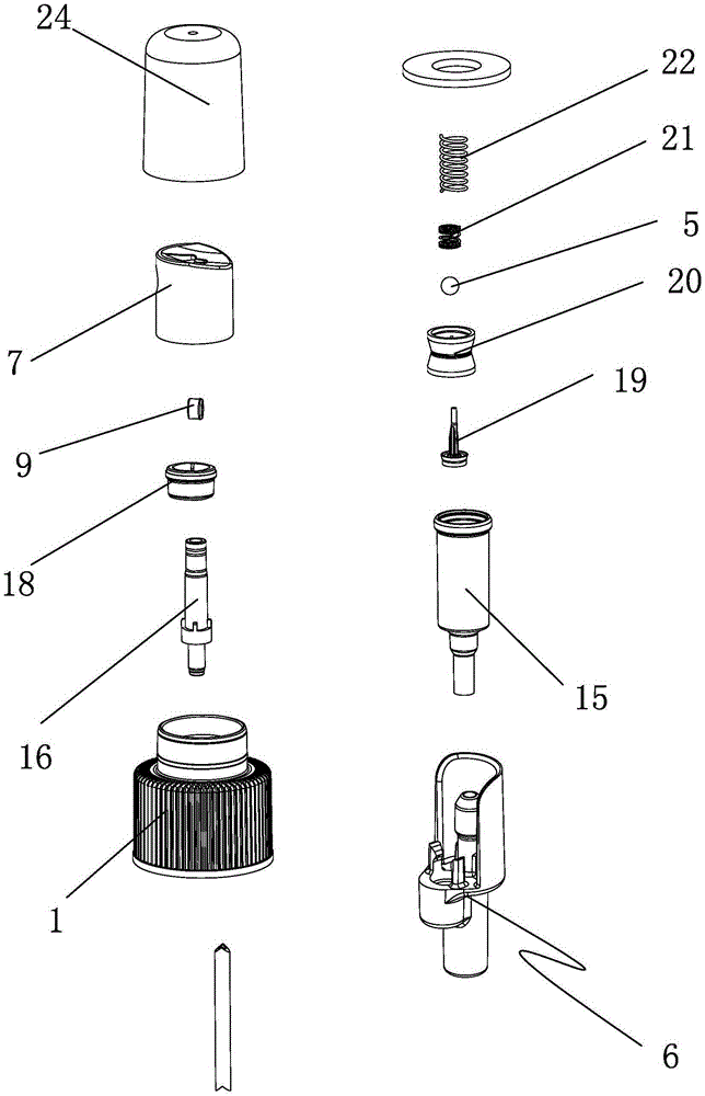
Examples
Embodiment approach
[0033] The first embodiment of the connection mechanism 25 of the present invention includes an accommodating groove 26 arranged in the bottle lock cap 1, a spring 27 is arranged in the accommodating groove 26, and a spring 27 is connected to the upper end of the spring 27. An elastic cord 28 , one end of the elastic cord 28 is connected to the outer cover 24 .
[0034] In the first embodiment of the connection mechanism 25 of the present invention, the connection mechanism 25 includes a chute 29 opened on the inner wall of the outer cover 24, and a connection bar 30 is provided on the outer convex connection ring 23, and a connection bar 30 is provided on the connection A limiting slider 31 is arranged on the end of the bar 30 , and the limiting slider 31 is movably arranged in the slide groove 29 .
[0035] In the present invention, a positioning groove 32 is provided on the lower end surface of the positioning ring platform 17 , and the upper end of the secondary spring 21 ...
PUM
 Abstract
Description
Claims
Application Information