A system and method for realizing optical network fault monitoring

A fault monitoring and optical network technology, applied in transmission systems, electromagnetic wave transmission systems, electrical components, etc., can solve the problems of long monitoring time and difficult to accept monitoring time, achieve low cost, reduce network monitoring cost, and expandability Good results

Inactive Publication Date: 2017-11-17
SPACE STAR TECH CO LTD +1
View PDF14 Cites 0 Cited by
  • Summary
  • Abstract
  • Description
  • Claims
  • Application Information

AI Technical Summary

Problems solved by technology

Fault monitoring in the upper layer protocol has a long monitoring time due to its relatively complex signaling, but it is difficult to accept such a long monitoring time in actual engineering applications

Method used


Image

  • A system and method for realizing optical network fault monitoring
  • A system and method for realizing optical network fault monitoring
  • A system and method for realizing optical network fault monitoring

Examples


Embodiment 1

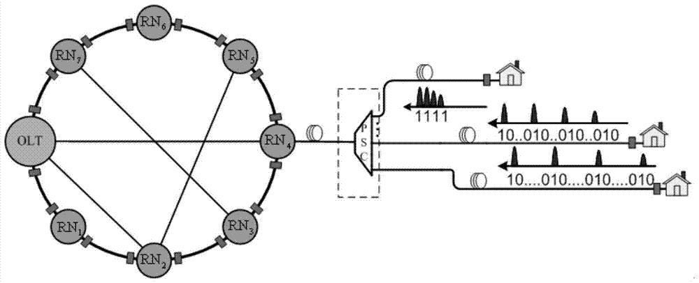
[0033] A system for realizing fault monitoring of an optical network, comprising a mesh network formed by connecting an optical link terminal OLT and a plurality of remote nodes RN and a power distribution coupler PSC, between the remote node RN and the power distribution coupler PSC Connected through optical fibers; the power distribution coupler PSC is connected with end users through a tree topology network.

Embodiment 2

[0035] A method for realizing optical network fault monitoring, comprising the following steps:

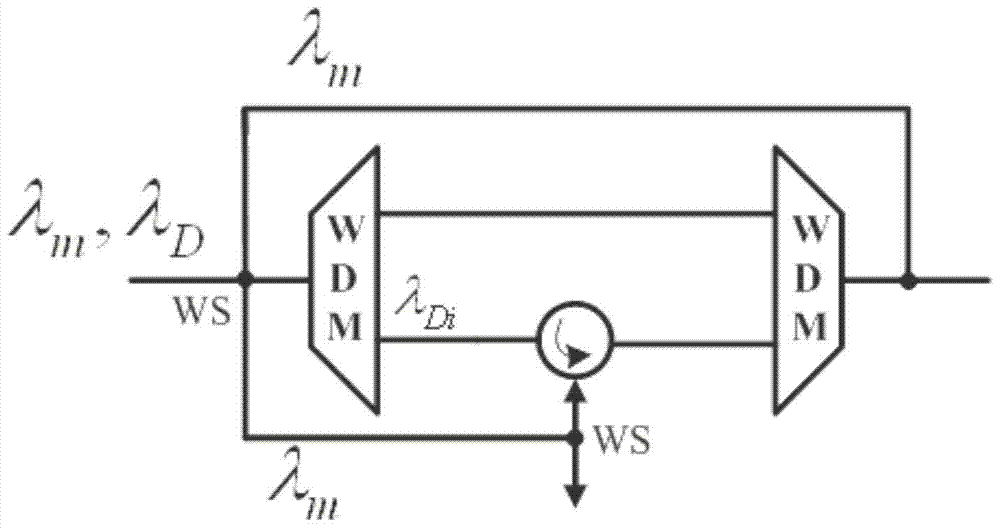
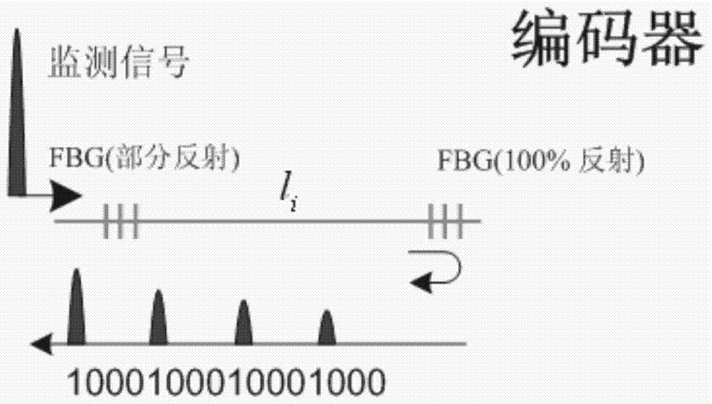
[0036] (1) Design quasi-orthogonal periodic codes that are different from each other and have a maximum cross-correlation coefficient of 1, and a dual fiber grating FBG encoder and FBG decoder corresponding to the quasi-orthogonal periodic codes;

[0037] (2) The FBG encoders are respectively placed on both sides of the remote node RN of the mesh network ring and in front of the end user optical path; Links, branch links of the tree topology network and links between the remote node RN and the power distribution coupler PSC;

[0038] (3) The optical link terminal OLT transmits a U-band monitoring pulse, which is transmitted counterclockwise on the mesh network ring: each FBG encoder couples a part of the U-band monitoring pulse, correspondingly generates an optical code, and then transmits the The optical code is reflected to the optical link terminal OLT in the clockwise directi...


PUM


Abstract

The invention relates to a system for monitoring optical network faults in real time. The system comprises a mesh network formed by connecting an optical link terminal OLT with multiple far-end nodes RN, and a power distribution coupler PSC, wherein the far-end nodes RN and the power distribution coupler PSC are connected through fiber, and the power distribution coupler PSC is connected with a terminal user through the tree-shaped topology network. The mesh network and the tree-shaped topology network can not be effectively monitored through a single scheme in the prior art, nodes and links are included, for the monitoring time, the monitoring cost and scalability, advantages of a light track detection mechanism and a light coding mechanism are combined for use, and the full network effective fault monitoring can be solved in a simple and extensible scheme.

Description

technical field [0001] The invention relates to a system and method for realizing optical network fault monitoring, belonging to the technical field of optical network survivability. Background technique [0002] With the continuous development of Internet technology, the Internet carries more and more types of business and the volume of business is increasing. However, once the optical fiber link or network node in the network fails, it will cause a large amount of data loss and service interruption. Therefore, only by quickly monitoring and locating the failed optical fiber link, the routing protocols of each layer can adjust the route in time. , the data transmitted to the faulty link is transmitted through other links, so as to restore data transmission in time. [0003] In order to monitor network services, the network needs to have the ability to provide effective detection mechanisms for various types of errors. The network protocol model has a layered structure, an...

Claims


Application Information

Patent Timeline
Patent Type & Authority Patents(China)
IPC IPC(8): H04B10/077H04B10/071
CPCH04B10/071H04B10/077H04B10/0771H04B10/0773
Inventor 程子敬季伟李潇张世成
Owner SPACE STAR TECH CO LTD
Why Eureka
Try Eureka