

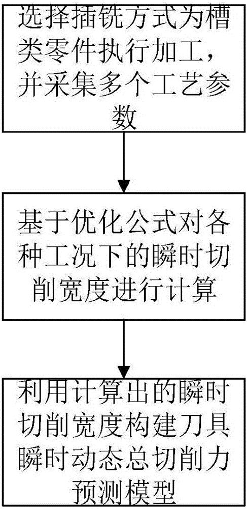
Plunge milling machining cutting force predicting and modeling method
A technology of cutting force prediction and modeling method, which is applied in the field of metal cutting processing, can solve the problems of restricting product quality, cutting force prediction is not accurate and comprehensive, and there are many constraints
- Summary
- Abstract
- Description
- Claims
- Application Information
AI Technical Summary
Problems solved by technology
Method used
Image

Examples
Embodiment Construction
[0026] In order to make the object, technical solution and advantages of the present invention clearer, the present invention will be further described in detail below in conjunction with the accompanying drawings and embodiments. It should be understood that the specific embodiments described here are only used to explain the present invention, not to limit the present invention. In addition, the technical features involved in the various embodiments of the present invention described below can be combined with each other as long as they do not constitute a conflict with each other.
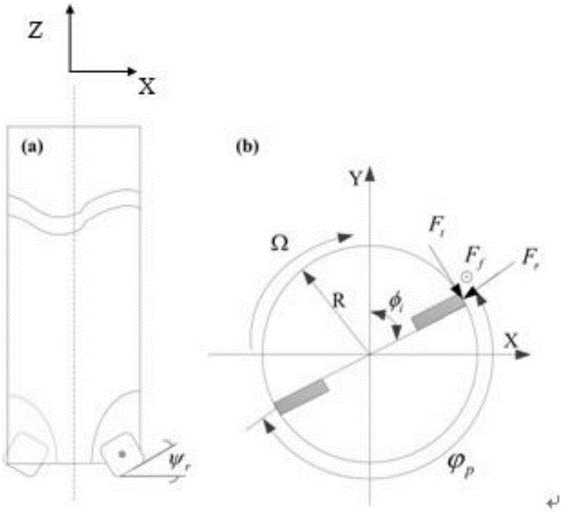
[0027] figure 2 is a schematic diagram showing the geometry of the tool used for plunge milling. Such as figure 2 As shown in , some main parameters related to this are listed, among which is the interdental angle of the plunge milling cutter, R represents the radius of the plunge milling cutter itself, F f is the feed force for plunge milling, F t is the tangential force along the direc...
PUM
 Abstract
Description
Claims
Application Information