Intelligent control method with predictive emissions monitoring ability

A control unit and a predetermined threshold technology, which are applied in the direction of fuel control, combustion method, and control combustion of turbine/propulsion devices, and can solve problems such as variable fuel composition without considering pilot fuel diversion fluctuations

Inactive Publication Date: 2016-07-06
SIEMENS AG
View PDF11 Cites 7 Cited by
  • Summary
  • Abstract
  • Description
  • Claims
  • Application Information

AI Technical Summary

Problems solved by technology

[0007] However, pilot fuel split fluctuations, drift across the fuel system, or changes in variable fuel composition are not considered in known predictive emissions monitoring systems

Method used


Image

  • Intelligent control method with predictive emissions monitoring ability
  • Intelligent control method with predictive emissions monitoring ability
  • Intelligent control method with predictive emissions monitoring ability

Examples


Embodiment Construction

[0050] The illustrations in the figures are schematic. It should be noted that similar or identical elements are provided with the same reference signs in different figures.

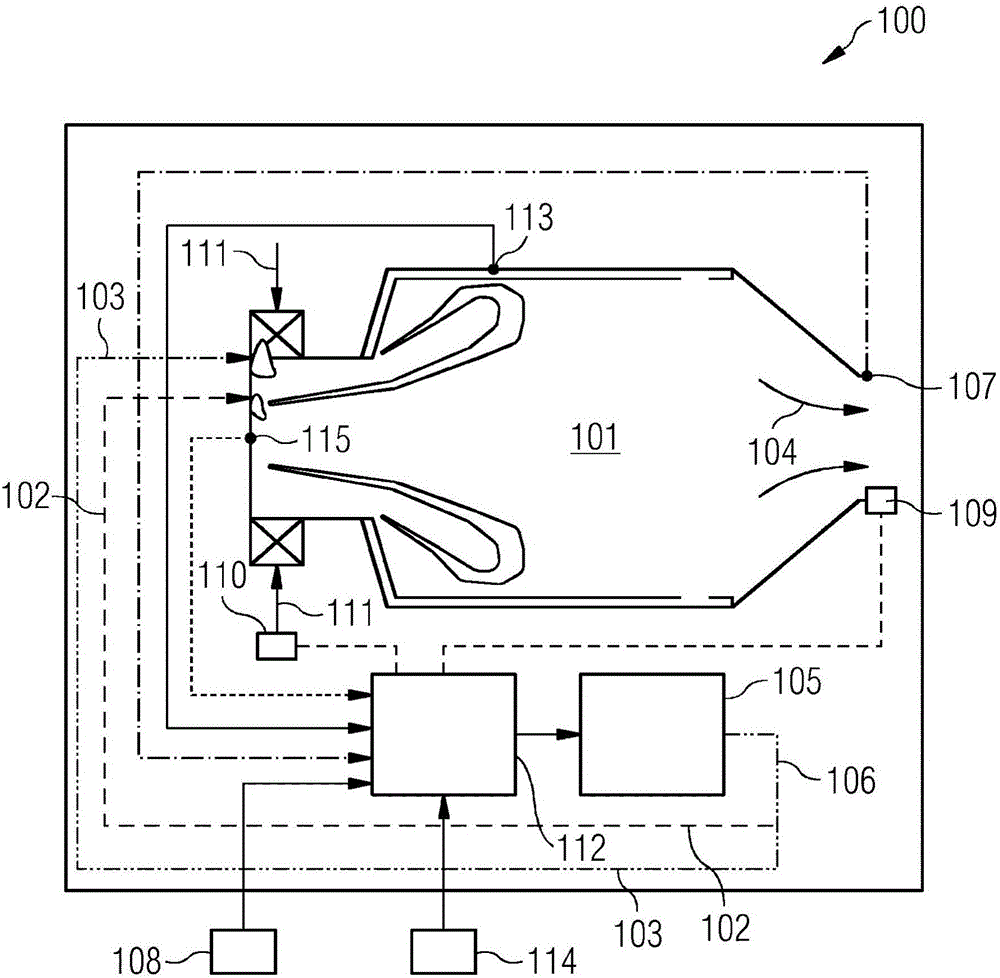
[0051] figure 1 A combustion system 100 for a gas turbine engine 10 is shown according to an exemplary embodiment of the invention. The combustion system 100 includes a combustion chamber 101 into which a pilot fuel 102 and a main fuel 103 may be injected and combusted therein. Exhaust gas 104 resulting from combusted pilot fuel 102 and combusted main fuel 103 may be exhausted from combustion chamber 101 . The fuel control unit 105 divides the fuel 106 into a pilot fuel 102 and a main fuel 103 in consideration of an adjustable pilot fuel / main fuel ratio. The temperature sensor 107 generates a temperature signal indicative of the temperature of the exhaust gas 104 at a location inside the combustion chamber 101 . The fuel determination unit 109 determines a fuel signal indicative of the fuel compositi...


PUM


Abstract

The present invention relates to a combustor system (100) for a gas turbine engine. The combustor system (100) comprises a combustion chamber (101) into which a pilot fuel (102) and a main fuel (103) is injectable and flammable, wherein an exhaust gas (104) generated by the burned pilot fuel (102) and the burned main fuel (103) is exhaustible out of the combustion chamber (101). A control unit (112) is coupled to a fuel control unit (105) for adjusting the pilot fuel (102) ratio. The control unit (112) is adapted for determining a predicted pollutant concentration of the exhaust gas (104) on the basis of a temperature signal, a fuel signal, a mass flow signal and a fuel split ratio.

Description

technical field [0001] The present invention relates to combustion systems and to a method for predicting the concentration of pollutants in a combustion system for a gas turbine engine. Background technique [0002] One goal in a gas turbine engine is to identify the optimum fuel split ratio between the pilot and main fuel injected into the combustion chamber so that the best gas turbine engine operation can be obtained. In particular, high metal temperatures and high dynamics in the combustion chamber are to be avoided, while increasing engine reliability with minimal production of pollutants such as NOx is desired. For example, low NOx mixture emissions can be obtained based on the use of lean primary fuels and extensive experience with known combustion systems. [0003] However, for regulatory purposes there is a need for the ability to predict pollutant emissions. Today, predictive emission monitoring systems are used, which predict pollutant emissions based on operat...

Claims


Application Information

Patent Timeline
Patent Type & Authority Applications(China)
IPC IPC(8): F23R3/34F02C7/228F02C9/28F02C9/34F23N5/18
CPCF02C9/34F05D2270/303F05D2270/306F05D2270/31F05D2270/44F23N2005/181F23N2221/10F23N2225/04F23N2225/08F23R3/343F23R2900/00013F23R3/00F23R3/34F05D2270/3061
Inventor G·布里克伍德G·布拉特
Owner SIEMENS AG
Why Eureka
Try Eureka