A hydrolysis acidification reactor with slag scraping function

A hydrolysis acidification and reactor technology, which is applied in chemical instruments and methods, anaerobic digestion treatment, biological water/sewage treatment, etc. problems, to achieve the effect of improving environmental sanitation, improving wastewater treatment effect, and reducing labor intensity

Active Publication Date: 2018-12-21
SHENYANG ACAD OF ENVIRONMENTAL SCI
View PDF4 Cites 0 Cited by
  • Summary
  • Abstract
  • Description
  • Claims
  • Application Information

AI Technical Summary

Problems solved by technology

[0004] The invention provides a hydrolytic acidification reactor with the function of scraping slag, which is used to solve the problems in the prior art that the scum on the surface of the hydrolytic acidification tank cannot be cleaned, which makes the labor intensity high, the wastewater treatment effect is not good, and the environmental sanitation is poor.

Method used


Image

  • A hydrolysis acidification reactor with slag scraping function
  • A hydrolysis acidification reactor with slag scraping function
  • A hydrolysis acidification reactor with slag scraping function

Examples


Embodiment 1

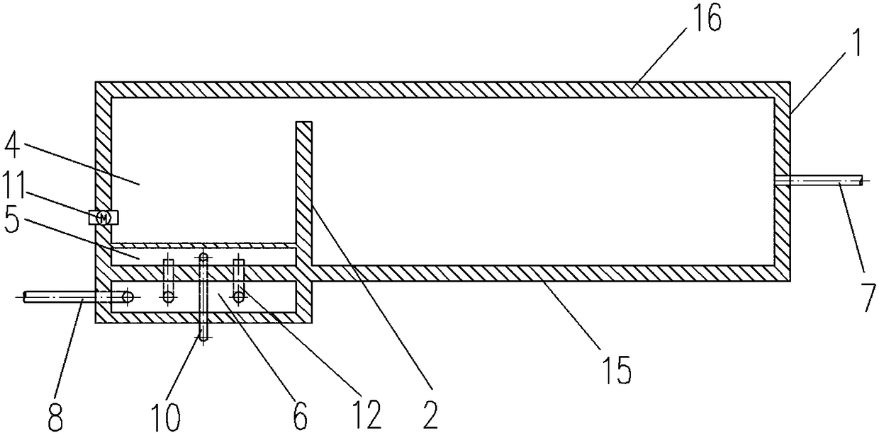
[0025] like figure 1 As shown, an exemplary hydrolytic acidification reactor with slag scraping function provided by the present invention is shown. The hydrolytic acidification reactor mainly includes: a pool body 1, in which a first Partition wall 2, one side of the first partition wall 2 joins with the front wall 15 of the pool body 1, and there is a certain distance between the other side and the rear wall 16 of the pool body 1, and the first partition wall 2 separates the pool body 1 into The plug flow packing area and the scraping slag outlet area 4; the plug flow packing area is provided with a water inlet pipe 7, the water inlet pipe 7 passes through the pool wall of the pool body 1 and connects the pool body 1 and the outside, and the sewage is passed into the hydrolysis acidification reaction through the water inlet pipe 7 In the device, the sewage is continuously passed into the pool, so that the phenomenon of push flow is formed in the hydrolysis acidification pool...

Embodiment 2

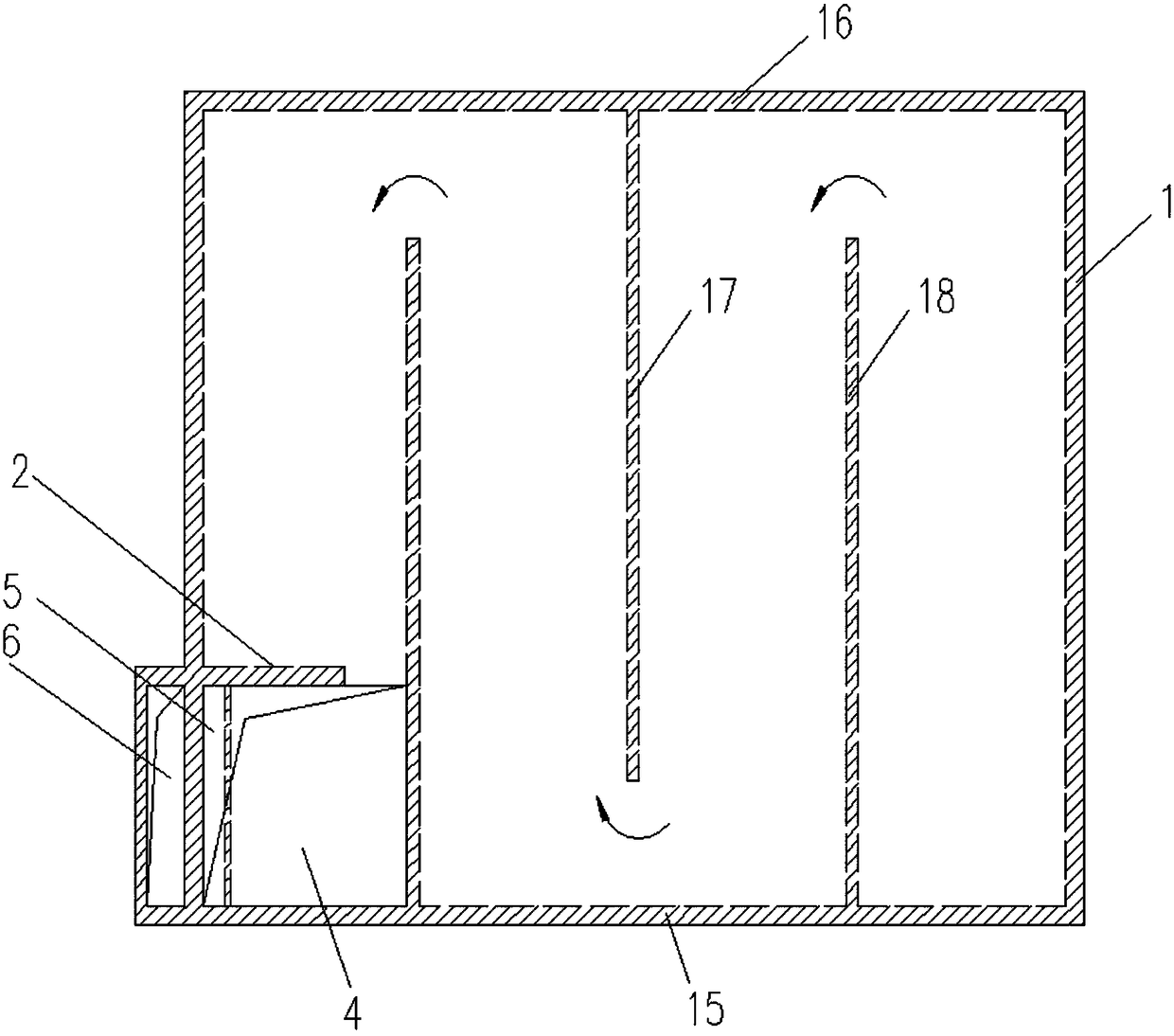
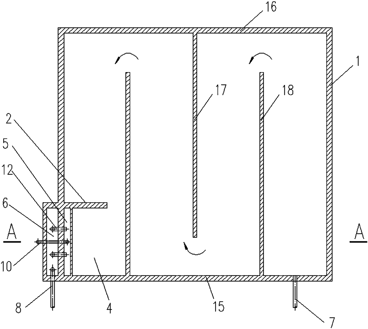
[0031] like Figure 2-Figure 4 As shown, an exemplary hydrolytic acidification reactor with slag scraping function provided by the present invention is shown. The hydrolytic acidification reactor mainly includes: a pool body 1, in which a first Partition wall 2, one side of the first partition wall 2 joins with the front wall 15 of the pool body 1, and there is a certain distance between the other side and the rear wall 16 of the pool body 1, and the first partition wall 2 separates the pool body 1 into Plug-flow packing area and scraping slag outlet area 4, at least one second partition wall 17 and at least one third partition wall 18 are arranged in the plug-flow packing area, and one side of the second partition wall 17 is in contact with the rear wall 16 of the pool body 1 There is a certain distance between the other side and the front wall 15 of the pool body 1, one side of the third partition wall 18 is connected to the front wall 15 of the pool body 1, and the other si...


PUM


Abstract

The invention discloses a hydrolytic acidification reactor with a residue scraping function, and relates to the technical field of sewage treatment. The hydrolytic acidification reactor comprises a reactor body, wherein a first partitioning wall is arranged in the reactor body; the first partitioning wall is used for partitioning the reactor body into a plug-flow packing area and a residue scraping water outlet area; a water inlet tube is arranged on the wall of the plug-flow packing area in a penetration manner; a residue tank, a sludge discharge tube, a residue discharge tube and a residue scraping device are arranged in the residue scraping water outlet area; the residue tank is arranged in a manner of being perpendicular to the first partitioning wall; the sludge discharge tube is communicated with the residue scraping water outlet area and the outside; the residue discharge tube is communicated with the residue tank and the outside; the residue scraping device is arranged at the top of the residue scraping water outlet area; a water outlet tank is arranged tightly close to the residue tank on the outer side of the reactor body; a communicating tube and a water outlet tube are arranged at the bottom of the water outlet tank; the communicating tube is used for communicating the water outlet tank with the residue scraping water outlet area; the water outlet tube is used for communicating the water outlet tank and the outside. By adoption of the hydrolytic acidification reactor disclosed by the invention, surface floating residues can be effectively eliminated, the working intensity of cleaning operators is alleviated, and meanwhile the environment sanitation is remarkably improved.

Description

technical field [0001] The invention relates to the technical field of sewage treatment, in particular to a hydrolysis acidification reactor with the function of scraping slag. Background technique [0002] With the rapid expansion of the dairy processing industry and the sharp increase in fresh milk processing, the water consumption and wastewater discharge of the dairy industry have also increased significantly. Dairy industry wastewater mainly comes from the washing water discharged during milk transportation and processing and the flushing water of processing equipment. The main components of wastewater are protein, lactose, fat, etc., and do not contain toxic and harmful substances and suspended substances of large particles. The existence state of protein, lactose and fat in wastewater is the same as that in raw milk. Lactose forms a true solution, protein forms a colloidal solution, and fat forms an emulsion. Dairy waste water is milky white, and fresh waste water i...

Claims


Application Information

Patent Timeline
Patent Type & Authority Patents(China)
IPC IPC(8): C02F3/28
CPCC02F3/28C02F3/2806C02F3/2866
Inventor 王允妹单连斌赵勇娇魏春飞陈明
Owner SHENYANG ACAD OF ENVIRONMENTAL SCI
Why Eureka
Try Eureka