A lock control ball valve

A ball valve and lock control technology, applied in valve details, valve devices, devices to prevent accidental or unauthorized action, etc., can solve the problems of easy loss of screws and cumbersome operations, and achieve the elimination of hidden dangers of screw loss, simple operation, and easy operation. The effect of compact structure

Active Publication Date: 2018-11-20
CHONGQING SHANCHENG GAS EQUIP
View PDF9 Cites 0 Cited by
  • Summary
  • Abstract
  • Description
  • Claims
  • Application Information

AI Technical Summary

Problems solved by technology

However, the valve can only be unlocked after removing the locking screw, which has the disadvantages of cumbersome operation and easy loss of the screw

Method used


Image

  • A lock control ball valve
  • A lock control ball valve
  • A lock control ball valve

Examples


Embodiment 1

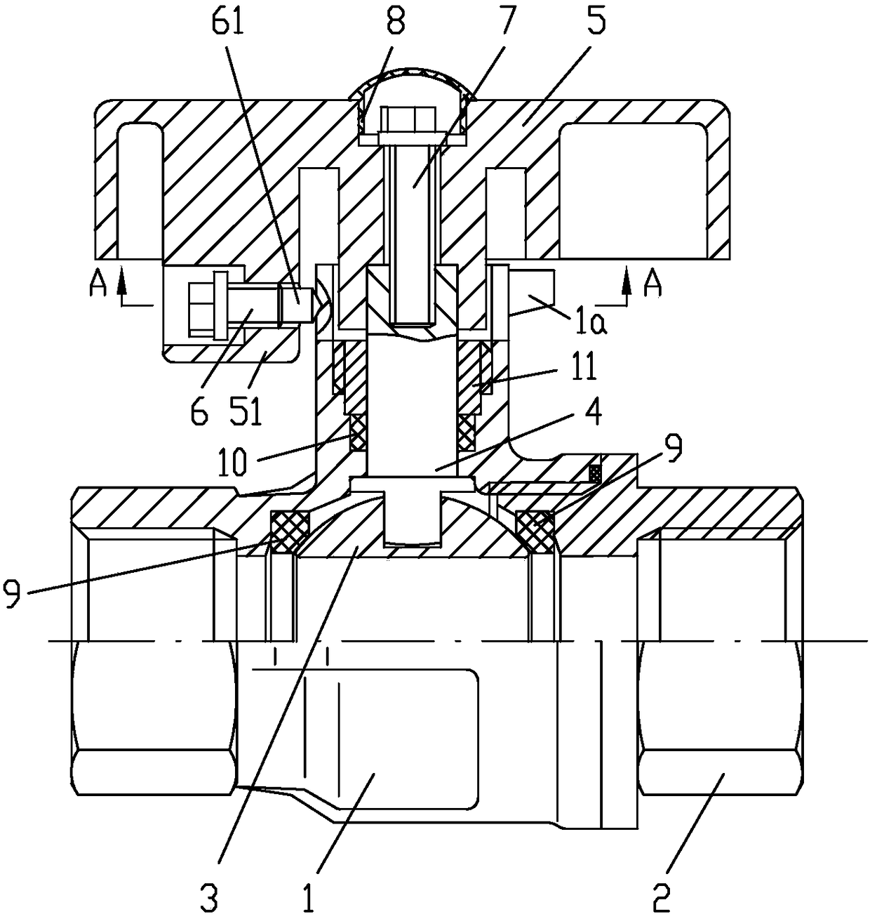
[0016] Example 1, see figure 1 , figure 2 , image 3 , a lock control ball valve, comprising a valve body 1 and a valve cover 2, a valve core 3 is connected between the valve body 1 and the valve cover 2 through a sealing seat ring 9, and a wrench 5 is connected to the valve core 3 through a valve stem 4; the valve body One side of 1 is formed with a stuffing chamber, and the valve stem 4 is located in the stuffing chamber, and a sealing packing 10 is provided between the outer circumference of the valve stem 4 and the inner wall of the packing chamber, and the sealing packing 10 is compressed by the packing nut 11 to form the valve stem 4 and the valve. The sealing connection between body 1; the wrench 5 is T-shaped, and the wrench 5 is set on the outer end of the valve stem 4 through the vertical part in the middle of the T-shape, and forms a torque transmission structure through two parallel flat surfaces, and the valve stem 4 The outer end of the valve body 1 is hidden ...

Embodiment 2

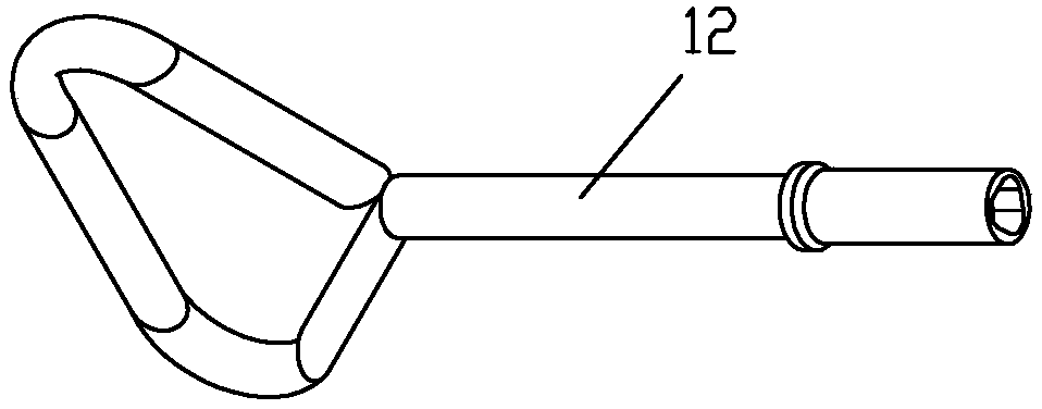
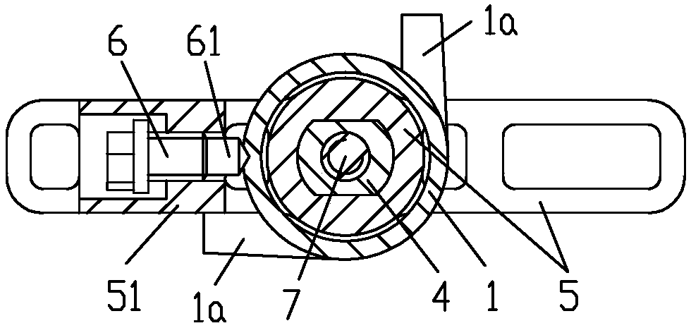
[0019] Example 2, see Figure 4 , the locking screw 6 is screwed on the outer wall of the stuffing chamber of the valve body 1, and the limit stop tongue 51 is located outside the head of the lock screw 6, so that when the lock screw 6 is tightened, the wrench 5 can rotate, and the limit stop tongue There is a perforation 52 horizontally on the 51, and the diameter of the perforation 52 is larger than the outer diameter of the screw opening tool 12 that can be inserted into the section, so that the locking screw 6 can be turned by the screw opening tool 12, so that the head of the locking screw 6 can extend into a part of the perforation 52, Thereby, the locking of the wrench 5 is formed; or, the locking screw 6 is twisted by the screw opening tool 12, so that the head of the locking screw 6 escapes from the perforation 52 and is positioned inside the limit stop tongue 51, thereby releasing the locking state of the wrench 5.

[0020] The rest of the structure of this embodimen...


PUM


Abstract

The invention discloses a lock control ball valve. The lock control ball valve comprises a valve body, a valve cover and a valve element. A wrench is connected to the valve element through a valve rod, the valve rod is located in a filling bin arranged on one side of the valve body, and the wrench is provided with a limiting stopping tongue for limiting the rotation angle scope of the wrench; a locking screw is arranged between the limiting stopping tongue and the outer wall of the filling bin of the valve body, a screwing structure in a triangular prism or four-pedal plum column shape is formed at the head of the locking screw, and the locking screw is used for locking the wrench through the outer wall of the filling bin; and the wrench only can be unlocked when the locking screw is separated from the outer wall of the filling bin or the limiting stopping tongue. The lock control ball valve has the beneficial effects that the locking screw can only be unscrewed with a special opening tool, the valve is effectively prevented from being opened due to maloperation or being opened arbitrarily, and the using safety of a user is guaranteed; in addition, the opening tool is small in structural size, convenient to carry, small in force and long in service life and brings convenience to locking and unlocking operation; and the hidden danger of losing the locking screw is avoided.

Description

technical field [0001] The invention relates to a ball valve, in particular to a lock control ball valve. Background technique [0002] Ball valve is a commonly used valve in the chemical industry, gas transmission, urban gas supply, and tap water supply pipelines. It has simple structure, reliable switch and long service life. Therefore, it is widely used in the above fields. Ordinary structure ball valves can be directly controlled by users as needed, and have control freedom and flexibility for direct users, but they lose control for gas supply and water supply management units. When the front-end engineering construction is not completed or the gas and water supply conditions are not met, after the valve is misoperated or operated without authorization, there will be safety hazards of tap water and gas leakage, or the risk of being stolen. The existing means of preventing unauthorized opening of the valve mainly includes designing the valve stem pulling interface as a ...

Claims


Application Information

Patent Timeline
Patent Type & Authority Patents(China)
IPC IPC(8): F16K5/06F16K35/00
CPCF16K5/06F16K35/00
Inventor 赵小波
Owner CHONGQING SHANCHENG GAS EQUIP
Why Eureka
Try Eureka