an antenna system

An antenna system and antenna technology, applied in the directions of antenna grounding device, antenna grounding switch structure connection, radiation element structure, etc., can solve the problems of antenna system wiring form limitation, low space utilization rate of electronic equipment, poor flexibility of antenna system, etc. , to achieve the effect of being conducive to radiation, meeting the frequency band requirements, and diverging energy distribution

Active Publication Date: 2018-05-11
VIVO MOBILE COMM CO LTD
View PDF3 Cites 0 Cited by
  • Summary
  • Abstract
  • Description
  • Claims
  • Application Information

AI Technical Summary

Problems solved by technology

[0004] In practical applications, for electronic devices with metal frames, consumers have higher and higher requirements for metal texture. At the same time, there are strict requirements for the length, width and thickness of electronic devices. The routing pattern poses a large limitation
In the case where the wiring form is limited, the flexibility of the antenna system is poor, which makes the space utilization rate inside the electronic device low, thus affecting the bandwidth of the antenna system

Method used


Image

  • an antenna system
  • an antenna system
  • an antenna system

Examples


Embodiment 1

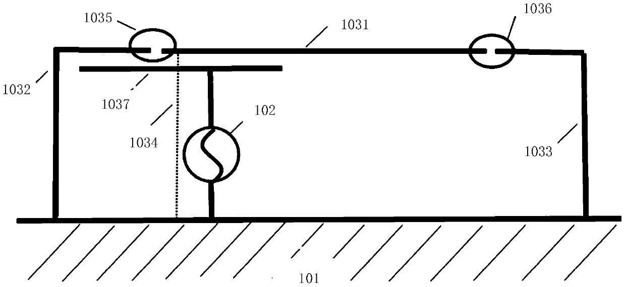
[0024] refer to figure 1 , which shows a schematic structural diagram of Embodiment 1 of an antenna system according to the present invention, which may specifically include: a mainboard ground 101, an antenna feed 102, and an antenna;

[0025] Wherein, the above-mentioned antenna may specifically include: a first antenna branch 1031, a second antenna branch 1032, a third antenna branch 1033, a ground path 1034 of the first antenna branch 1031, a first break 1035, a second break 1036 and a coupling antenna branch 1037 ;

[0026] The above-mentioned antenna feed source 102 is connected between the above-mentioned coupling antenna branch 1037 and the above-mentioned main board ground 101; the above-mentioned first fracture 1035 is arranged between the above-mentioned first antenna branch 1031 and the above-mentioned second antenna branch 1032, and the above-mentioned second fracture 1036 is arranged on Between the first antenna branch 1031 and the third antenna branch 1033, the...

Embodiment 2

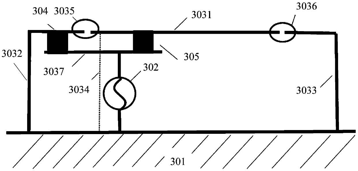
[0043] refer to image 3 , which shows a schematic structural diagram of Embodiment 2 of an antenna system according to the present invention, which may specifically include: a mainboard ground 301, an antenna feed 302, an antenna, a first lumped element 304, and a second lumped element 305;

[0044] Wherein, the above-mentioned antenna 303 may specifically include: a first antenna branch 3031, a second antenna branch 3032, a third antenna branch 3033, a ground path 3034 of the first antenna branch 3031, a first break 3035, a second break 3036, a coupling antenna branch 3037;

[0045] Wherein, the above-mentioned antenna feed 302 is connected between the above-mentioned coupling antenna branch 3037 and the above-mentioned main board ground 301; the above-mentioned first fracture 3035 is connected between the above-mentioned first antenna branch 3031 and the above-mentioned second antenna branch 3032, and the above-mentioned second fracture 3036 Connected between the first ant...


PUM


Abstract

The present invention provides an antenna system, including: a mainboard ground, an antenna feed, and an antenna; the antenna includes: a first antenna branch, a second antenna branch, a third antenna branch, a ground path of the first antenna branch, A first break, a second break and a coupling antenna branch; wherein, the antenna feed is connected between the coupling antenna branch and the main board ground, and the first break is set between the first antenna branch and the Between the second antenna branches, the second opening is arranged between the first antenna branch and the third antenna branch, and the second antenna branch and the third antenna branch are respectively connected to the ground of the main board , the ground path of the first antenna branch is connected between the first antenna branch and the main board ground; the lengths of the first antenna branch, the second antenna branch and the third antenna branch are different same. The embodiments of the present invention can increase the bandwidth of the antenna system.

Description

technical field [0001] The invention relates to the technical field of electronic equipment, in particular to an antenna system. Background technique [0002] With the development of science and technology, electronic devices such as mobile phones and tablet computers play an increasingly important role in people's daily life. [0003] Antenna systems are an important part of electronic equipment for transmitting and receiving electromagnetic waves. For example, during a call on a mobile phone, the sound signal can be converted into an electromagnetic wave signal through the mobile phone's oscillator, and then transmitted through the antenna system; and the antenna signal can be converted into a sound signal after receiving the electromagnetic wave signal through the mobile phone's detector . [0004] In practical applications, for electronic devices with metal frames, consumers have higher and higher requirements for metal texture. At the same time, there are strict requi...

Claims


Application Information

Patent Timeline
Patent Type & Authority Patents(China)
IPC IPC(8): H01Q1/50H01Q1/38H01Q1/36H01Q1/48
Inventor 蒋锐
Owner VIVO MOBILE COMM CO LTD
Why Eureka
Try Eureka