Optical sensing module, optical sensing accessory, and optical sensing device

A sensing module and optical sensing technology, applied in optical sensors, sensors, measuring devices, etc., can solve the problems of poor signal-to-noise ratio of optical sensing modules, improve light output efficiency and reduce low signal-to-noise ratio Effect

Active Publication Date: 2016-08-24
TAIWAN BIOPHOTONIC
View PDF11 Cites 3 Cited by
  • Summary
  • Abstract
  • Description
  • Claims
  • Application Information

AI Technical Summary

Problems solved by technology

[0004] In summary, the signal-to-noise ratio of the optical sensor module will be poor

Method used


Image

  • Optical sensing module, optical sensing accessory, and optical sensing device
  • Optical sensing module, optical sensing accessory, and optical sensing device
  • Optical sensing module, optical sensing accessory, and optical sensing device

Examples


Embodiment Construction

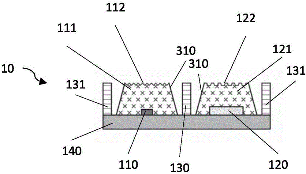
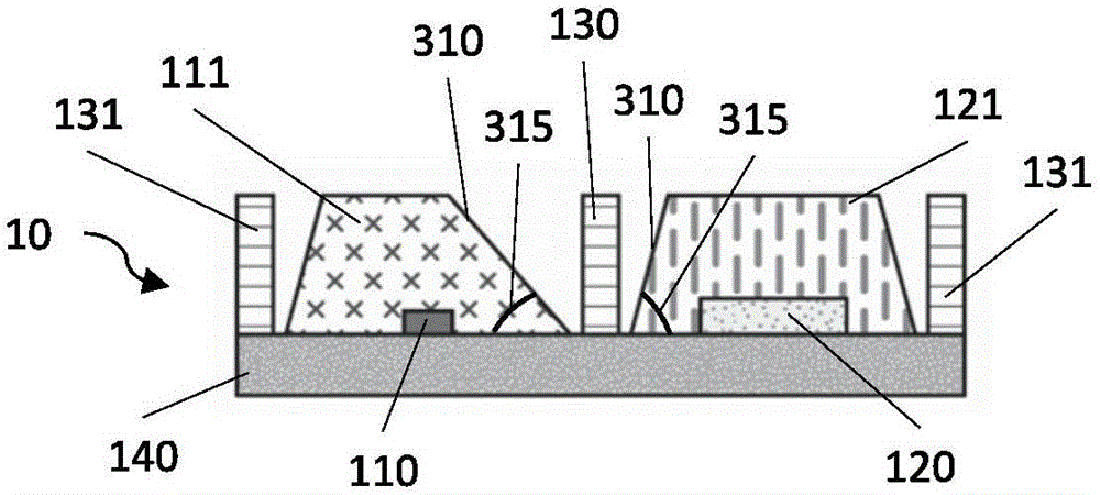
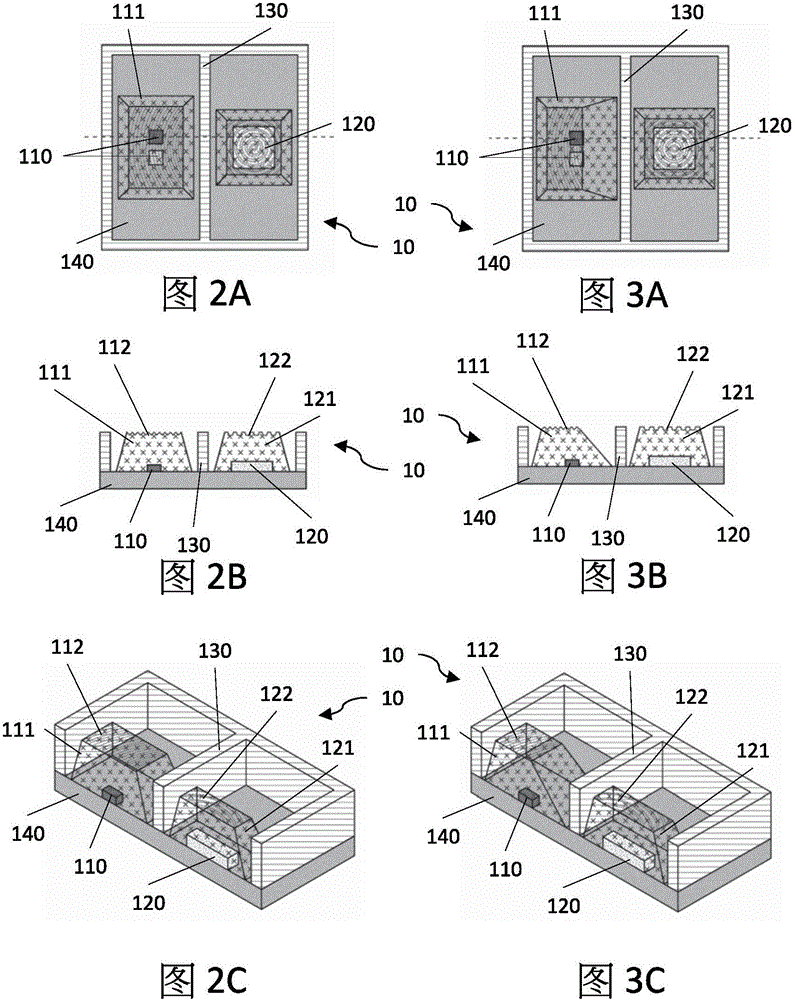
[0149] For concise and clear description, where appropriate, the same reference numerals are repeatedly used in different drawings to designate corresponding or similar components. Furthermore, numerous specific details were set forth in the description in order to provide a thorough understanding of the embodiments described herein. It will be understood, however, by those skilled in the art that the embodiments described herein may operate without these specific details. In other cases, some methods, procedures and components have not been described in detail so as not to obscure the technical features being described. The drawings do not necessarily need to be the same size as the real thing. The proportions of certain parts of the drawings may be exaggerated to better illustrate details and technical features. What is described in the specification should not be considered as limiting the scope of the embodiments described herein.

[0150] Several definitions applicable...


PUM


Abstract

The present disclosure relates to an optical sensing module, an optical sensing accessory, and an optical sensing device. A reflective optical sensor module comprises a light source and a first encapsulant, a photodetector and a second encapsulant, an electrode and a substrate. The light source is configured to convert electric power into radiant energy and to emit light to an object surface. The photodetector is configured to receive the light from an object surface and to convert radiant energy into electrical current or voltage. The electrode is configured to detect an external circuit formed by the contact with an object surface. The optical sensing accessory and the optical sensing device comprise the reflective optical sensor module and other electronic modules to have further applications.

Description

technical field [0001] The invention relates to an optical sensing module, an optical sensing accessory, an optical sensing device and related applications. Background technique [0002] The basic principle of the reflective optical sensor module is that light is emitted from the light source and projected onto the object to be measured, and the photodetector receives and measures the amount of reflected light, calculates it and converts it into an electrical signal. Generally speaking, the light incident on the object under test can be reflected, refracted, absorbed or scattered by the object. As long as part of the reflected light, refracted light and scattered light is received by the photodetector of the optical sensor module, it can be converted into a signal and used for measurement. [0003] When calculating the signal noise ratio (Signal Noise Ratio, SNR), the above-mentioned signals corresponding to the reflected light and the scattered light are defined as the sig...

Claims


Application Information

Patent Timeline
Patent Type & Authority Applications(China)
IPC IPC(8): H01L23/31H01L25/16A61B5/296A61B5/332
CPCH01L23/31H01L27/144H01L23/3114H01L25/165H01L25/167A61B5/0059G01N21/33G01N21/35A61B5/14552A61B5/681H01L31/0203H01L31/02325H01L31/02327H01L31/173A61B2560/0443A61B2562/0233A61B2562/164A61B2562/227G01J1/0209G01J1/0407G01J1/029G01J1/0411G01J3/36G01J1/0488G01J1/0214G01J1/0459G01J1/08H01L33/54G01J1/44H04B10/071G01J1/0437G01J1/4228G01J1/0271H01L31/0232H01L31/125H01L33/58
Inventor 曲昌盛黎育腾李业文范植训钟隆斌陈治诚钟双兆
Owner TAIWAN BIOPHOTONIC
Why Eureka
Try Eureka