Pneumatic impact type vibrator

A vibrator and impact technology, applied in the direction of fluid using vibration, can solve the problems of short service life, low efficiency of air impact hammer, easy to wear and so on, and achieve the effect of long service life, strong vibration effect and simple structure

Active Publication Date: 2016-09-21
佛山市特亚菲科技有限公司
View PDF6 Cites 4 Cited by
  • Summary
  • Abstract
  • Description
  • Claims
  • Application Information

AI Technical Summary

Problems solved by technology

[0004] However, in the above-mentioned air impact hammer, the upper part of the piston impact rod is equipped with two O-rings and two wear-resistant rings, affected by the friction between the O-rings, wear-resistant rings and the inner wall of the cylinder, the reset of the piston impact rod is relatively slow , directly affects the number of impacts of the piston impact rod per unit time, resulting in low efficiency of the air impact hammer, and, under long-term friction between the O-ring and the wear-resistant ring, it is easy to wear
Once the gap between the O-ring, wear-resistant ring and the inner wall of the cylinder is greater than the pressure gap of the compressed air, the air impact hammer will lose its impact force and its service life is short. It is only suitable for places where there is no technical requirement

Method used


Image

  • Pneumatic impact type vibrator
  • Pneumatic impact type vibrator
  • Pneumatic impact type vibrator

Examples


Embodiment Construction

[0020] The present invention will be further described below in conjunction with the drawings and embodiments.

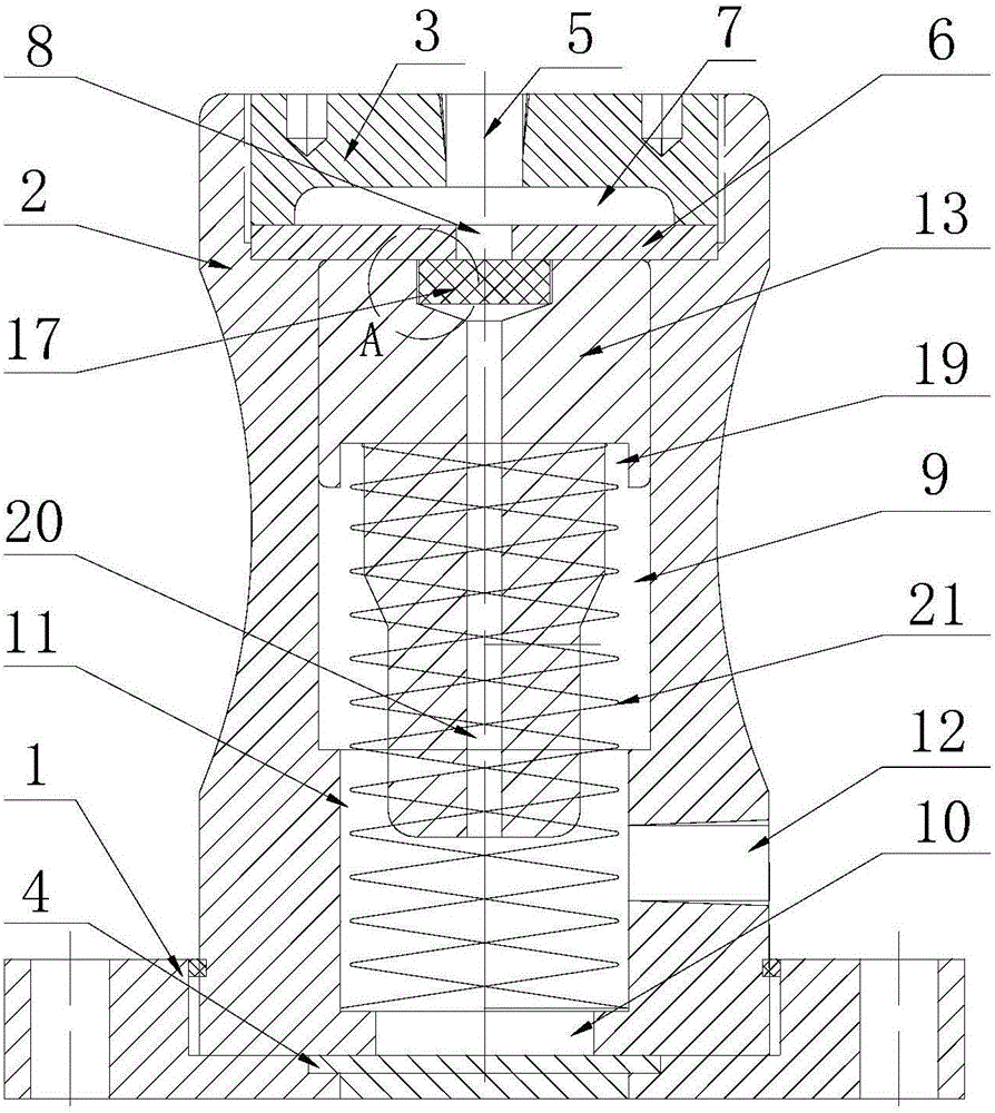
[0021] Such as Figure 1~3 As shown in the pneumatic shock type vibrator, the vibrator's shell is composed of a base 1, a cylinder block 2 and a top cover 3. The base 1 is made of aluminum alloy material, and the cylinder block 2 is mounted on the base 1 and passes through The O-ring forms a sealed connection, and an impact plate 4 as an impact block is also installed on the base 1. The impact plate 4 is made of anti-collision steel plate; the cylinder block 2 is made of hard aluminum alloy, and the cylinder block 2 is provided with a hollow The cavity and the inner wall of the cylinder block 2 are subjected to abrasion resistance treatment; the top cover 3 is installed on the top of the cylinder block 2 and is sealed with the cylinder block 2 through a screw connection. The top cover 3 is provided with an air inlet 5.

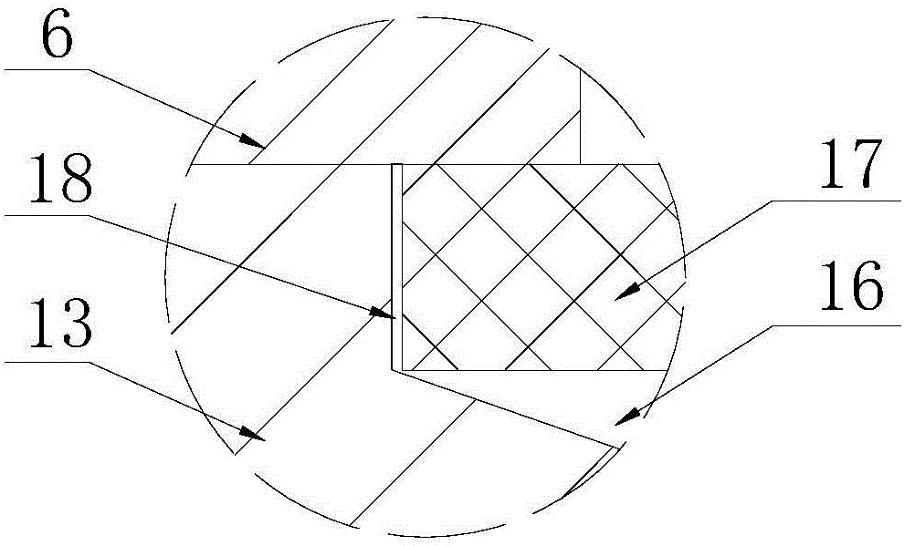
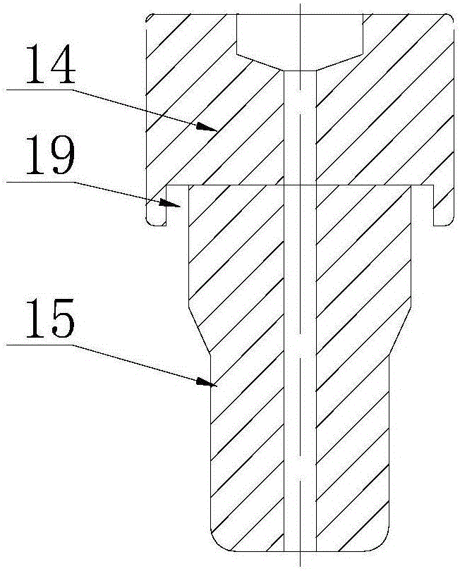
[0022] A pressure plate 6 is fixed between the to...


PUM


Abstract

The invention discloses a pneumatic impact type vibrator which comprises a shell, wherein a pressure block which is made of metal is arranged in the shell; in the shell, a pressure strengthening cavity which is close to the top part of the shell is formed in one side of the pressure block, and an impact cavity is formed in the other side of the pressure block; a pressure block gas passing hole which communicates with the pressure strengthening cavity is formed in the pressure block; a piston impact rod which can impact the bottom of the shell in a reciprocating manner is arranged in the impact cavity; an elastic piece used for resetting is installed at one end of the piston impact rod; a permanent magnetic meson which is matched with the pressure block is arranged at the other end of the piston impact rod; a ventilation channel is formed between the permanent magnetic meson and the piston impact rod and communicates with the pressure block gas passing hole; an impact rod gas passing hole used for communicating the impact cavity with the ventilation channel is also formed in the piston impact rod; a gas inlet which communicates with the pressure strengthening cavity and an exhaust hole which communicates with the impact cavity are also formed in the shell. The pneumatic impact type vibrator has the advantages of long service life, strong vibration effect, capability of realizing strong vibration by gas inlet without high pressure and the like.

Description

Technical field [0001] The invention relates to the field of pipeline transportation, in particular to a pneumatic impact vibrator. Background technique [0002] In addition to being widely used in long-distance transportation of oil and natural gas, pipeline transportation can also transport ore, coal, building materials, chemicals, mud, ceramic slurry, food fluids and grains, etc. Pipeline transportation has obvious advantages. Its transportation volume is large, continuous, rapid, economical, safe, reliable, stable, low investment, small footprint, low cost, and can realize automatic control and is widely used. However, pipeline transportation has obvious shortcomings due to clogging. Therefore, the drag reduction problem of pipeline transportation is a major problem that plagues people, and it has attracted more and more attention. [0003] At present, pipeline transportation, especially the pipeline transportation of materials, usually adopts the method of installing a vibra...

Claims


Application Information

Patent Timeline
Patent Type & Authority Applications(China)
IPC IPC(8): B06B1/18
CPCB06B1/183
Inventor 向友刚
Owner 佛山市特亚菲科技有限公司
Why Eureka
Try Eureka