

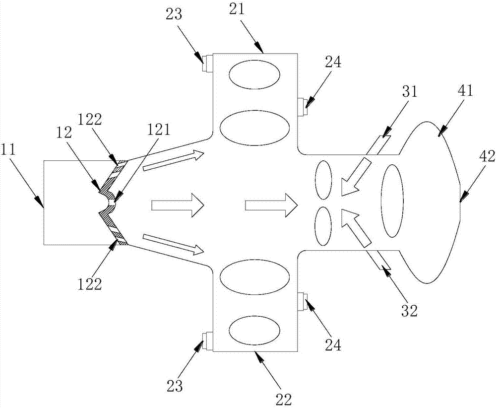
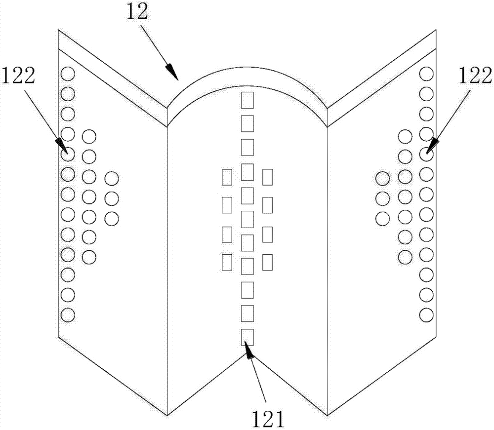
A dual-cavity flame-stabilized combustion device based on air-staged reverse jet technology
A reverse jet, flame stabilization technology, applied in the combustion chamber, combustion method, combustion equipment and other directions, can solve the problems of the unstable combustion area of the cavity, the fuel residence time is not long, the single air inlet of the combustion chamber, etc., to avoid The effect of high local temperature, widening the stable combustion range and widening the application range
- Summary
- Abstract
- Description
- Claims
- Application Information
AI Technical Summary
Problems solved by technology
Method used
Image

Examples
Embodiment Construction
[0024] In order to make the technical means, creative features, goals and effects achieved by the present invention easy to understand, the present invention will be further described below in conjunction with specific illustrations.
[0025] In describing the present invention, it is to be understood that the terms "longitudinal", "radial", "length", "width", "thickness", "upper", "lower", "front", "rear", The orientation or positional relationship indicated by "left", "right", "vertical", "horizontal", "top", "bottom", "inner", "outer", etc. is based on the orientation or positional relationship shown in the drawings , is only for the convenience of describing the present invention and simplifying the description, but does not indicate or imply that the referred device or element must have a specific orientation, be constructed and operated in a specific orientation, and thus should not be construed as limiting the present invention. In the description of the present inventi...
PUM
 Abstract
Description
Claims
Application Information