Method for improving effective thermal efficiency of engine and power transmission mechanism prepared through same

A technology of power transmission and thermal efficiency, applied in the direction of machine/engine, mechanical equipment, etc., can solve the problem of small improvement of the effective thermal efficiency of the engine, and achieve the effect of less parts, large power improvement, and favorable combustion and compression ratio.

Active Publication Date: 2018-09-21
张佰力
View PDF9 Cites 5 Cited by
  • Summary
  • Abstract
  • Description
  • Claims
  • Application Information

AI Technical Summary

Problems solved by technology

Although the engine power transmission mechanisms of these structures have their own advantages, their shortcomings still exist. For example, there are alternating side pressures between the piston and the cylinder wall of the unbiased engine of the single crankshaft structure, which affects the friction between the piston and the cylinder liner. Power consumption, statistics show that this kind of friction power consumption accounts for about 75% of the mechanical loss of the engine, and the friction power consumption of the cylinder liner and piston ring accounts for 50% of the piston connecting rod system. Therefore, in order to reduce the pressure on the side of the piston, the crankshaft is usually used However, it can be seen from the disclosed technical solutions that the offset crankshaft structure can generally eliminate the side pressure of the engine piston and cylinder wall, reduce friction and vibration, because those skilled in the art believe that the power stroke is when the crankshaft rotates The greater the proportion of the angle, the more work is done, so the crankshaft-connecting-rod mechanism only rotates in the direction of positive bias to do work
However, these engine power transmission mechanisms arranged in a positive bias manner have a small increase in the effective thermal efficiency of the engine

Method used


Image

  • Method for improving effective thermal efficiency of engine and power transmission mechanism prepared through same
  • Method for improving effective thermal efficiency of engine and power transmission mechanism prepared through same
  • Method for improving effective thermal efficiency of engine and power transmission mechanism prepared through same

Examples


Embodiment 1

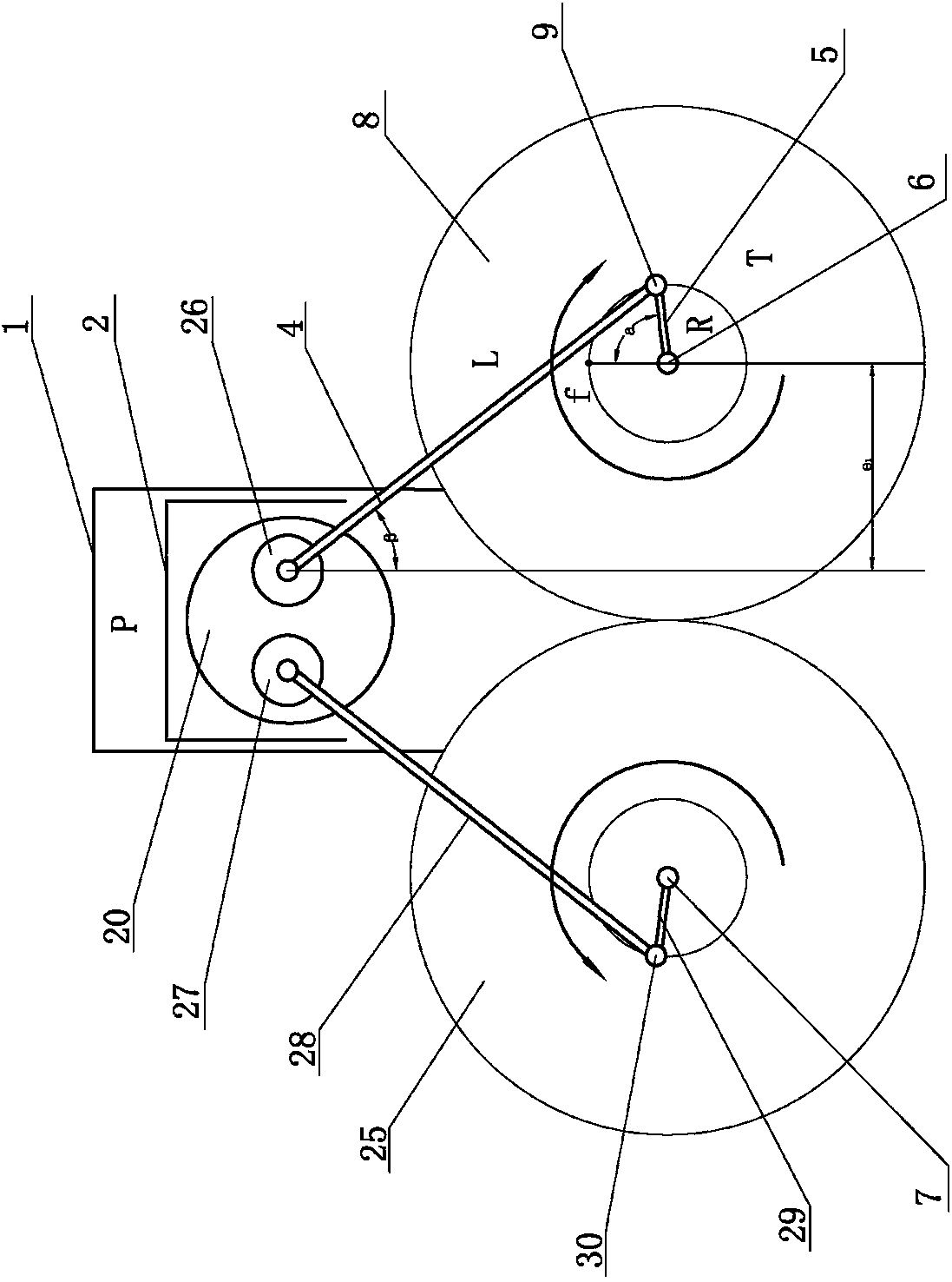
[0074] Embodiment 1: it has the first cylinder 1, the first piston 2 is installed in the first cylinder 1, the circular slider 20 is installed on the first piston, the first pin shaft 26 and the second pin shaft 27 are installed on the circular slider 20, the first The pin shaft 26 is connected with one end of the first crank connecting rod 4, the other end of the first crank connecting rod 4 is connected with one end of the first crank 5 through the first crank shaft 9, and the other end of the first crank 5 is connected with the first crankshaft 6, The first crankshaft 6 is fixedly connected to the first synchronous gear 8, and the distance between the axis of the first crankshaft 6 and the axis of the connecting end of the first pin 26 and the first crank connecting rod 4 is the first eccentricity e 1 The second pin shaft 27 is connected with one end of the second connecting rod 28 of the crank, the other end of the second crank connecting rod 28 is connected with one end of...

Embodiment 2

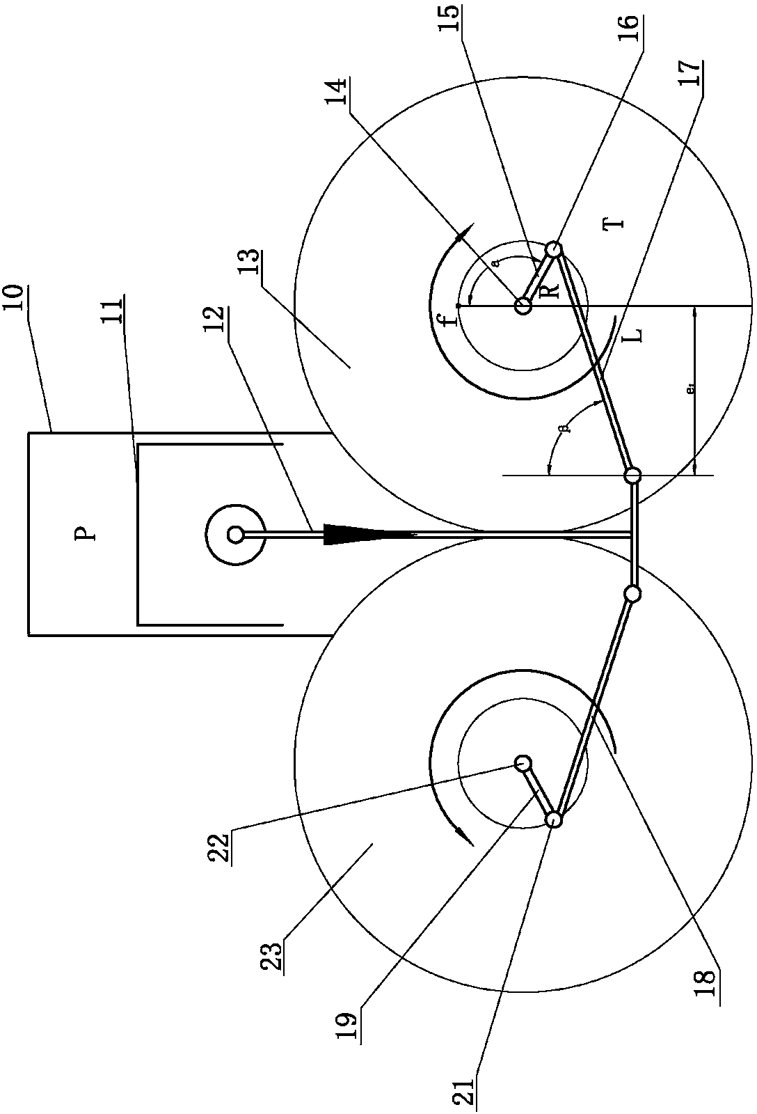
[0075] Embodiment two: it has a second cylinder 10, a second piston 11 is installed in the second cylinder 10, the second piston 11 is connected with one end of the piston rod 12, and the other end of the piston rod 12 is connected with the third crank connecting rod 17 and the fourth crank rod 17 respectively. One end of the crank connecting rod 18 is connected, the other end of the third crank connecting rod 17 is connected with one end of the third crank 15 through the third crank shaft 16, the other end of the third crank 15 is connected with the third crank shaft 14, and the other end of the fourth crank connecting rod 18 The fourth crankshaft 21 is connected to one end of the fourth crank 19, and the other end of the fourth crank 19 is connected to the fourth crankshaft 22. The third crankshaft 14 is synchronously fixedly connected to the third gear 13, and the fourth crankshaft 22 is synchronously fixedly connected to the fourth gear 23. , the third crankshaft 14 rotates...

Embodiment 3

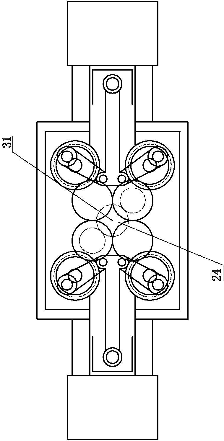
[0076] Embodiment three; as attached image 3 The structure shown is a horizontally opposed scheme of the negative bias anti-pull structure described in the second embodiment. In order to reduce the volume, the directly coupled synchronous third gear 13 and fourth gear 23 are replaced by two intermediary gears meshing , the intermediate gear meshes with the central gear 24 after deceleration, and outputs power through the central output shaft 31.


PUM


Abstract

The invention discloses a method for improving effective thermal efficiency of an engine and a power transmission mechanism prepared through the method. An eccentric distance is set between each crankshaft axis in the power transmission mechanism of the engine and the connection end axis between a piston rod and a corresponding crank connecting rod or between each crankshaft axis and the connection end axis between the pin shaft center on each piston and the corresponding crank connection rod. The power transmission mechanism is large in power increase amplitude, oil consumption is saved, andexhaust contaminant is low; power is high, and the torque is large; the working stroke is accelerated, combustion and increase of the compression ratio are facilitated, and the heat loss is reduced; the number of parts is small, and the production cost is low; the length of the connection rods can be reduced, and the overall mechanism is compact; when crankshafts rotate in a negative offset manner, lubricating oil splashed through the crankshafts can face pistons all the time, a piston cylinder body is good in lubrication, heat dissipation of engine oil to the pistons is high, the work intensity of the engine is large, the service life is long, and the like.

Description

technical field [0001] The invention relates to an engine, and relates to a method for improving the effective thermal efficiency of the engine and a power transmission mechanism prepared therefor. Background technique [0002] Various engine power transmission mechanisms that have been disclosed at present all convert the reciprocating motion of the piston into rotary motion through the crank-connecting rod mechanism and the crankshaft, and the crankshaft is driven by the piston-connecting rod to perform work. Among these structures, there are single-crankshaft and double-crankshaft structures, and specifically, non-biased and biased structures. Although the engine power transmission mechanisms of these structures have their own advantages, their shortcomings still exist. For example, there are alternating side pressures between the piston and the cylinder wall of the unbiased engine of the single crankshaft structure, which affects the friction between the piston and the c...

Claims


Application Information

Patent Timeline
Patent Type & Authority Applications(China)
IPC IPC(8): F02B75/32
CPCF02B75/32
Inventor 张佰力张玉川
Owner 张佰力
Why Eureka
Try Eureka